Nissan Sentra Owners Manual: Trip computer
When the ignition switch is placed in the ON
position, the modes of the  trip
trip
computer can be
selected by pressing the button on the
steering wheel. The following modes can be selected:
- Trip A
- Trip B
- ECO Pedal Indicator
- Instant fuel economy
- Average fuel economy
- Average speed
- Distance to empty
- Trip computer reset
Trip A
Measures the distance of one specific trip.
Trip B
Measures the distance of a second specific trip.
ECO Pedal Indicator Display
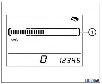
Use the ECO Pedal Indicator 1 for improving fuel economy.
When the ECO Pedal Indicator bar is in the green range, it displays the recommended accelerator pedal position to optimize fuel economy.
If the ECO Pedal Indicator bar is out of green range, the vehicle will not provide optimized fuel economy.
NOTE:
The ECO Pedal Indicator’s bar is not displayed when the cruise control is in operation.
Instant fuel economy
The instant fuel economy mode shows the instant fuel economy. The display updates instantly when driving.
Average fuel economy
The average fuel economy mode shows the average
fuel economy since the last reset. Resetting
is done by pressing the  button on
the
steering wheel for more than approximately
1 second. The display is updated every 30 seconds.
At about the first 1/3 mile (500 m) after a reset, the display shows (----).
Average speed
The average speed mode shows the average
vehicle speed since last reset. Resetting is done
by pressing the  button on the
steering
wheel for more than approximately 1 second. The
display is updated every 30 seconds. The first
30 seconds after a reset, the display shows
(----).
Distance to empty
The distance to empty (dte) mode provides you with an estimation of the distance that can be driven before refueling. The dte is constantly being calculated, based on the amount of fuel in the fuel tank and the actual fuel economy.
The display is updated every 30 seconds.
NOTE:
When driving uphill or rounding curves, the fuel in the tank shifts, which may momentarily change the display.
Trip computer reset
To reset Trip A, Trip B, AVG/mpg, or AVG/mph,
go to the desired mode on the trip computer and
hold the  button on the steering
wheel for
more than 3 seconds.
 Fuel gauge
NOTE:
The ignition switch must be placed in the
ON position for the gauge to give a reading.
The gauge indicates the approximate fuel level
in the tank.
The gauge may move slightly during bra ...
 Outside temperature display
The outside temperature function provides a display
of the outside temperature when the ignition
switch is placed in the ON position.
The display of positive temperatures is unsigned
(blank), ne ...
Other materials:
Primary speed sensor
Exploded View
Transaxle assembly
O-ring
Primary speed sensor
: Always replace after every
disassembly.
: N m (kg-m, in-lb)
: Genuine NISSAN CVT Fluid NS-3
Removal and Installation
REMOVAL
Disconnect the primary speed sensor connector.
Remove the primary speed sensor.
...
The low washer fluid warning lamp does not turn on or off
Description
The low washer fluid warning lamp is still illuminated even after washer
fluid is added.
The low washer fluid warning lamp is not illuminated even though the
washer tank is empty.
Diagnosis procedure
1.Check washer fluid level switch signal circuit
Check the washer fluid ...
U1000 Can comm circuit
Description
CAN (Controller Area Network) is a serial communication line for real-time
application. It is an on-vehicle multiplex
communication line with high data communication speed and excellent malfunction
detection ability.
Many electronic control units are equipped onto a vehicle, an ...
