Nissan Sentra B18 (2020-2025) Service Manual: Transaxle Assembly
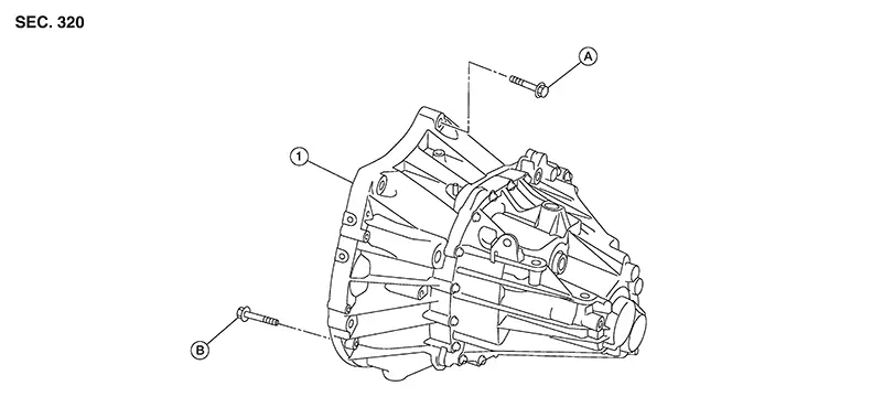
Exploded View
|
1. |
Transaxle assembly |
A. |
Refer to Removal and Installation |
B. |
Refer to Removal and Installation |
Removal and Installation
Warning:
Do not remove the radiator cap when the engine is hot. Serious burns could occur from high pressure coolant escaping from the radiator. Wrap a thick cloth around the cap. Slowly turn it a quarter turn to allow built-up pressure to escape. Carefully remove the cap by turning it all the way.
CAUTION:
Do not reuse CSC (Concentric Slave Cylinder). The CSC (Concentric Slave Cylinder) slides back to the original position every time the transaxle assembly is removed. This action may allow dust or contaminants to gather on the sliding parts and damage a seal of CSC (Concentric Slave Cylinder) causing clutch fluid leakage.
Note:
When removing components such as hoses, tubes/lines, etc., cap or plug openings to prevent fluid from spilling.
REMOVAL
Shift the shift lever to the neutral position.
Remove the engine assembly together with transaxle assembly from the Nissan Sentra vehicle. Refer to Removal and Installation.
Disconnect the park/neutral position (PNP) switch (neutral switch) harness connector.
Remove the starter motor. Refer to Removal and Installation.
Remove the clutch tube from CSC (Consentric Slave Cylinder). Refer to Exploded View.
Remove the transaxle assembly and engine assembly bolts. Refer to Exploded View.
Remove transaxle assembly from the engine assembly.
Remove engine mounting insulator (LH). Refer to Exploded View.
Remove CSC (Concentric Slave Cylinder). Refer to Removal and Installation.
INSTALLATION
Installation is in the reverse order of removal.
CAUTION:
-
When replacing an engine or transaxle you must make sure any dowels are installed correctly during re-assembly
-
The transaxle assembly must not interfere with the wire harnesses and clutch tube.
-
Improper alignment caused by missing dowels may cause vibration, oil leaks or breakage of drive train components.
-
When installing transaxle assembly, do not bring input shaft into contact with clutch cover.
-
Tapping work for tapping bolts is not applied to new transaxle case. Do not perform tapping by other than screwing tapping bolts because tapping is formed by screwing tapping bolts into transaxle case.
Tighten transaxle assembly mounting bolts to the specified torque. As shown viewing from the engine.
|
Bolt symbol |
(A) |
(B) |
|---|---|---|
|
Insertion direction |
Transaxle to engine |
Engine to transaxle |
|
Quantity |
3 |
6 |
|
Bolt length “ |
60 (2.36) |
50 (1.97) |
|
Tightening torque N·m (kg-m, ft-lb) |
62.0 (6.3, 46) |
|
 ” mm (in)
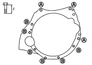
Inspection
Check the operation of the control linkage. Refer to Inspection.
Check the oil level and for oil leaks. Refer to Inspection.


Other materials:
ECU diagnosis information
Diagnosis sensor unit
DTC Index
DIAGNOSTIC CODE CHART
NOTE:
Follow the procedures in numerical order when repairing malfunctioning
parts. Confirm whether malfunction is
eliminated using air bag warning lamp or CONSULT each time repair is finished.
If malfunction is still
observed, proceed ...
Service
Service
Never use electrical test equipment to check SRS
circuits unless instructed to in this Service Manual.
Before servicing the SRS, place ignition switch
OFF, disconnect battery negative terminal and wait 3 minutes or
more.
For approxi ...
General Specifications
General Specifications
Unit: mm (in)
Master cylinder
Cylinder bore diameter
25.4 (1)
Brake booster
Diaphragm
...
