Nissan Sentra Service Manual: The door open warning continues displaying, or does not display
Description
- The door ajar warning is displayed even though all of the doors are closed.
- The door ajar warning is not displayed even though a door is ajar.
Diagnosis procedure
1.Check bcm input signal
Check the bcm input signal. Refer to dlk-102, "component function check" (with intelligent key) or dlk- 253, "component function check" (without intelligent key).
Is the inspection result normal? Yes >> go to 2.
No >> go to 3.
2.Check combination meter input signal
Select the METER/M&A Data Monitor and check the DOOR W/L monitor value while opening and closing doors.
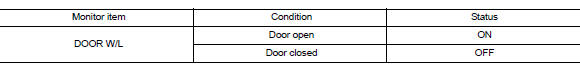
Is the inspection result normal? YES >> Replace combination meter. Refer to MWI-77, "Removal and Installation".
NO >> Replace BCM. Refer to BCS-73, "Removal and Installation" (with Intelligent Key) or BCS-126, "Removal and Installation" (without Intelligent Key).
3.Check door switch signal circuit
Check the door switch signal circuit. Refer to dlk-102, "diagnosis procedure" (with intelligent key) or dlk- 253, "diagnosis procedure" (without intelligent key).
Is the inspection result normal? Yes >> go to 4.
No >> repair or replace harness or connector.
4.Check door switch
Perform a unit check for the door switch. Refer to DLK-103, "Component Inspection" (with Intelligent Key) or DLK-255, "Component Inspection" (without Intelligent Key).
Is the inspection result normal? YES >> Replace combination meter. Refer to MWI-77, "Removal and Installation".
NO >> Replace applicable door switch. Refer to DLK-194, "Removal and Installation" (with Intelligent Key) or DLK-341, "Removal and Installation" (without Intelligent Key).
 The oil pressure warning lamp does not turn off
Description
The oil pressure warning lamp remains illuminated while the engine is running
(normal oil pressure).
Diagnosis procedure
1.Check combination meter input signal
Start the engine a ...
 The parking brake release warning continues displaying, or does not display
Description
The parking brake warning is displayed while driving the vehicle even
though the parking brake is released.
The parking brake warning is not displayed while driving the vehicle
...
Other materials:
P0705 Transmission range sensor A
DTC Logic
DTC DETECTION LOGIC
DTC
CONSULT screen terms
[Trouble diagnosis content]
DTC detection condition
Possible causes
P0705
T/M RANGE SENSOR A
[Transmission Range Sensor
A Circuit (PRNDL Input)]
Two or more range signals simultaneously
stay ON conti ...
Precaution for Work
When removing or disassembling each component, be careful not to damage
or deform it. If a component
may be subject to interference, be sure to protect it with a shop cloth.
When removing (disengaging) components with a screwdriver or similar
tool, be sure to wrap the component
with a ...
Fuel pressure
Work Procedure
FUEL PRESSURE RELEASE
1.FUEL PRESSURE RELEASE
With CONSULT
Turn ignition switch ON.
Perform “FUEL PRESSURE RELEASE” in “WORK SUPPORT” mode of “ENGINE” using
CONSULT
Start engine.
After engine stalls, crank it two or three times to release ...
