Nissan Sentra Service Manual: Rear suspension beam
Exploded View
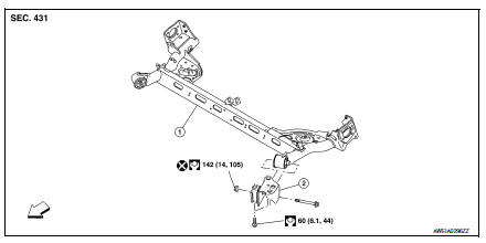
- Rear suspension beam
- Rear suspension arm bracket
 Front
Front
Removal and Installation
NOTE:
When removing components such as hoses, tubes, lines, etc., cap or plug openings to prevent fluid from spilling.
REMOVAL
- Remove the rear wheels and tires using power tool. Refer to WT-47, "Exploded View".
- Drain the brake fluid. Refer to CO-12, "Changing Engine Coolant".
- Disconnect the wheel sensor harness from the retainers. Remove the wheel sensors and position the wheel sensor harness aside. Refer to BRC-107, "REAR WHEEL SENSOR : Removal and Installation".
- Remove the brake caliper torque member bolts leaving the brake hoses attached. Position the brake calipers aside with wire (if equipped). Refer to BR-47, "BRAKE CALIPER ASSEMBLY : Removal and Installation".
CAUTION:
Do not depress the brake pedal when the brake caliper is removed.
- Put alignment marks (A) on the disc brake rotors and on the wheel hubs and bearings. Remove the disc brake rotors (if equipped).
CAUTION:
Do not drop the disc brake rotor.
- Remove the rear drum brake assemblies (if equipped). Refer to BR-42, "Removal and Installation".
- Remove the disc brake parking brake shoe assemblies (if equipped). Refer to PB-9, "Removal and Installation - Disc Brake".
- Disconnect the parking brake cables from the back plates, the rear suspension beam, and the body. Refer to PB-7, "Removal and Installation".
- Disconnect the brake hoses from the brake tubes on the rear suspension beam. Disconnect the brake hoses and the brake tubes from the brackets. Refer to BR-30, "REAR : Removal and Installation".
- Remove the wheel hubs and bearings. Refer to RAX-7, "Removal and Installation - Disc brake" (if equipped) or to RAX-6, "Removal and Installation - Drum brake" (if equipped).
- Set a suitable jack under the rear suspension beam.
CAUTION:
- At this step, the jack must be set only for supporting the removal procedure. For details on jacking up the vehicle, refer to GI-31, "Garage Jack and Safety Stand and 2-Pole Lift".
- Do not damage the rear suspension beam with the jack.
- Remove the lower shock absorber bolts. Refer to RSU-8, "Exploded View".
- Slowly lower the suitable jack. Remove the upper rubber seats, the coil springs, and the lower rubber seats from the rear suspension beam.
CAUTION:
Make sure the rear suspension beam is stable when using the jack.
- Remove the rear suspension arm bracket bolts.
- Slowly lower the suitable jack. Remove the rear suspension arm brackets and the rear suspension beam from the vehicle.
- Remove the rear suspension beam bolts and nuts.
- Remove the rear suspension arm brackets from the rear suspension beam.
- Inspect the components. Refer to RSU-14, "Inspection".
INSTALLATION
Installation is in the reverse order of removal.
CAUTION:
Do not reuse the rear suspension beam nuts.
- Perform the final tightening of the nuts and bolts under unladen conditions with the tires on level ground.
- Adjust the disc brake parking brake (if equipped). Refer to PB-11, "Inspection and Adjustment".
- Adjust the drum brake parking brake (if equipped). Refer to PB-4, "Inspection and Adjustment".
- Fill the hydraulic brake system. Refer to BR-17, "Drain and Refill".
- Bleed the hydraulic brake system. Refer to BR-17, "Bleeding Brake System".
- Complete the inspection. Refer to RSU-14, "Inspection".
Inspection
INSPECTION AFTER REMOVAL
Check the rear suspension beam and the rear suspension beam brackets for deformation, cracks or damage.
Replace the parts if necessary.
INSPECTION AFTER INSTALLATION
- Check the wheel sensor harness to be sure the connectors are fully seated.
- Check the neutral position of the steering angle sensor. Refer to BRC-54, "Work Procedure".
- Check the wheel alignment. Refer to RSU-6, "Inspection".
 Coil spring
Exploded View
Upper rubber seat
Coil spring
Lower rubber seat
Rear suspension beam
Front
Removal and Installation
REMOVAL
Set a suitable jack under the rear suspension beam.
...
 Service data and specifications (SDS)
Wheel Alignment (Unladen*1)
*1: Fuel, engine coolant, and lubricants are full. Spare tire, jack, hand
tools, and mats are in designated positions.
*2: Since an adjustment mechanism is not inc ...
Other materials:
Front combination lamp
Exploded View
Large cover (not serviceable)
Small cover (not serviceable)
Front combination lamp
Halogen lamp bulb (high beam)
Turn signal lamp bulb
Turn signal lamp bulb socket
LED harness connector
Halogen lamp bulb (high beam)
harness connector
Halogen lamp bulb (low bea ...
Cleaning exterior
In order to maintain the appearance of your vehicle,
it is important to take proper care of it.
To protect the paint surfaces, please wash your
vehicle as soon as you can:
after a rainfall to prevent possible damage
from acid rain.
after driving on coastal roads.
when contaminants suc ...
When traveling or registering your vehicle in another country
When planning to drive your NISSAN vehicle
in another country, you should first find
out if the fuel available is suitable for your vehicle’s
engine.
Using fuel with an octane rating that is too low
may cause engine damage. All gasoline vehicles
must be operated with unleaded gasoline. The ...
