Nissan Sentra B18 (2020-2025) Service Manual: System Description. Description
Description
Engine Cooling System
Engine Cooling System
-
The radiator adopts a side flow aluminum radiator core.
-
A drive belt is adopted for water pump operation.
-
A shallow bottom is adopted for the cylinder block water jacket for optimizing cooling performance.
-
An electric cooling fan is adopted. The cooling fan is controlled by signals from the ECM (engine control module).
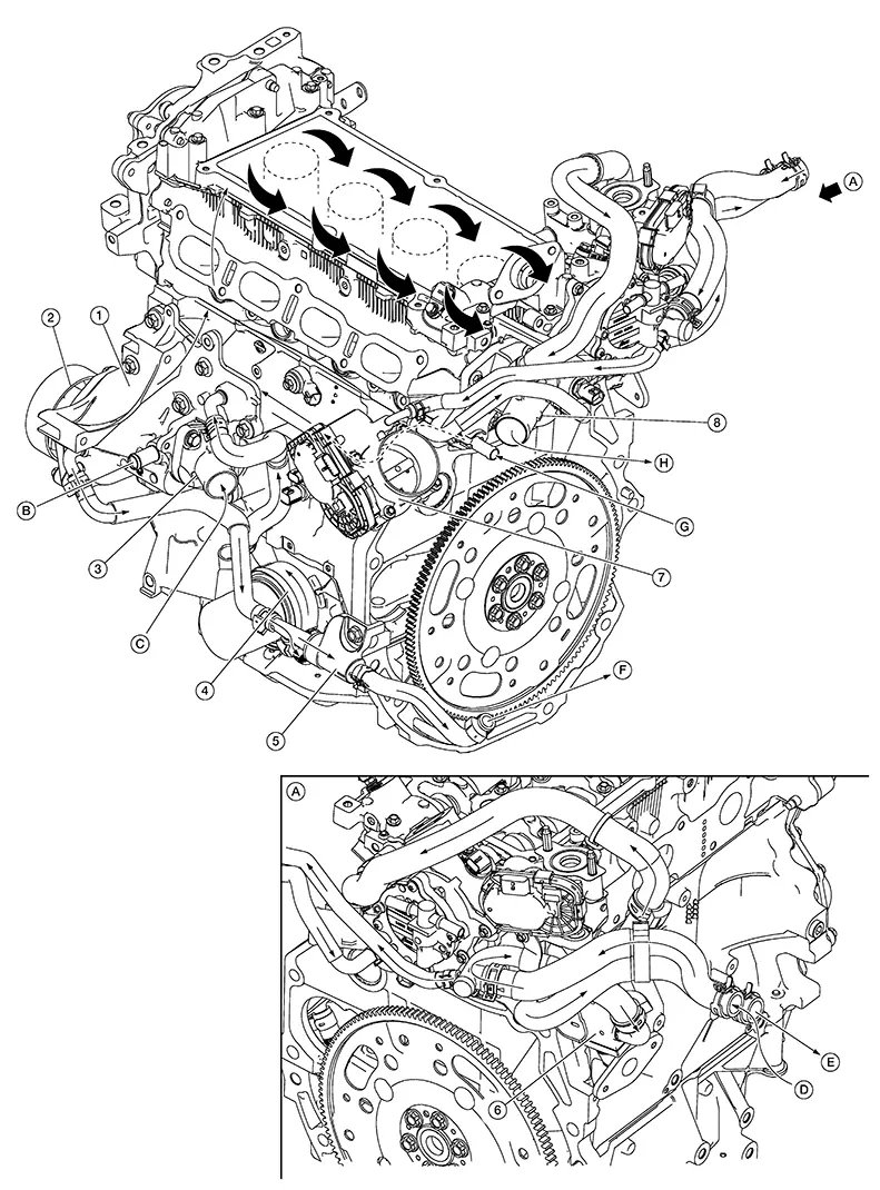
|
1. |
Water pump housing |
2. |
Water pump |
3. |
Water inlet |
|
4. |
Oil cooler |
5. |
Heater thermostat assembly (CVT models only) |
6. |
EGR cooler |
|
7. |
Electric throttle control actuator |
8. |
Water outlet |
A. |
View A |
|
B. |
From reservoir tank. Refer to Exploded View. |
C. |
From radiator. Refer to Exploded View. |
D. |
From heater core. Refer to Exploded View. |
|
E. |
To heater core. Refer to Exploded View. |
F. |
To CVT fluid warmer (CVT models only). Refer to Exploded View. |
G. |
From CVT fluid warmer (CVT models only). Refer to Exploded View. |
|
H. |
To radiator. Refer to Exploded View. |
Engine Cooling System Schematic
Engine Cooling System Schematic
CVT models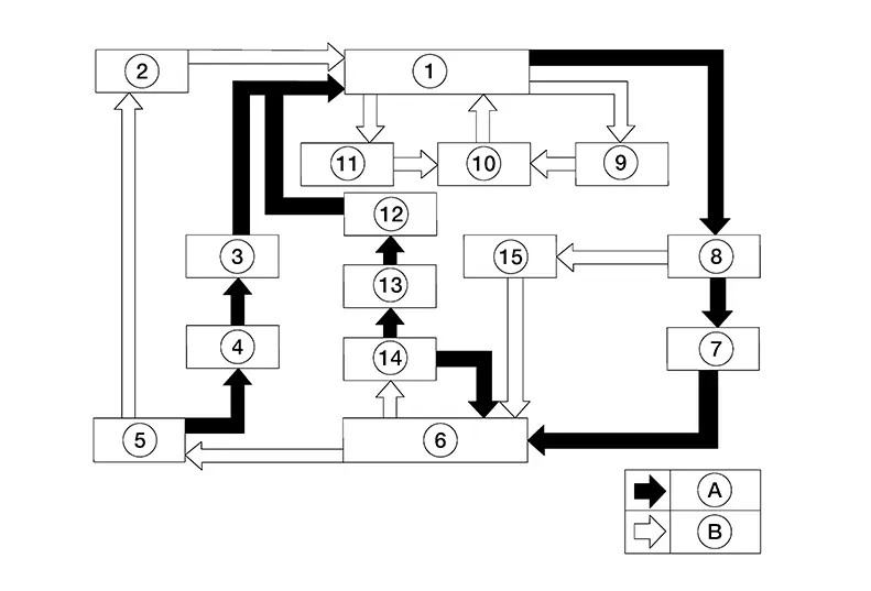
|
1. |
Water outlet |
2. |
Cylinder head |
3. |
Water control valve |
|
4. |
Cylinder block |
5. |
Water pump |
6. |
Water pump housing |
|
7. |
Water inlet |
8. |
Radiator |
9. |
Electric throttle control actuator |
|
10. |
EGR cooler |
11. |
Heater core |
12. |
CVT fluid warmer |
|
13. |
Heater thermostat assembly |
14. |
Oil cooler |
15. |
Reservoir tank |
|
A. |
High temperature |
B. |
Normal temperature |
|
1. |
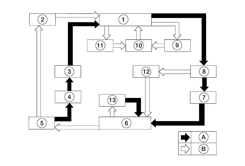
Water outlet |
2. |
Cylinder head |
3. |
Water control valve |
|
4. |
Cylinder block |
5. |
Water pump |
6. |
Water pump housing |
|
7. |
Water inlet |
8. |
Radiator |
9. |
Electric throttle control actuator |
|
10. |
EGR cooler |
11. |
Heater core |
12. |
Reservoir tank |
|
13. |
Oil cooler |
A. |
High temperature |
B. |
Normal temperature |
Other materials:
Diagnosis System (air Bag)
Description
Description
CAUTION:
Never use electrical test equipment on any
circuit related to the SRS unless instructed in this Service
Manual. SRS wiring harnesses can be identified by yellow and/or
orange harnesses or harness connectors.
...
B1360 Combination Meter
Dtc Description
DTC Description
DTC DETECTION LOGIC
DTC No.
CONSULT screen terms
(Trouble diagnosis
content)
DTC detection condition
...
Basic Inspection
Diagnosis and Repair Workflow
Work Flow
Work flow
OVERALL SEQUENCE
Reference 1: On Board Diagnosis Function.
Reference 2: DTC Index.
Reference 3: Diagnosis Procedure.
Reference 4: Component Inspection.
Reference 5 ...