Nissan Sentra Service Manual: System description
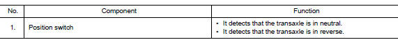
COMPONENT PARTS
Component Parts Location
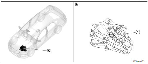
- Transaxle assembly
STRUCTURE AND OPERATION
Sectional View
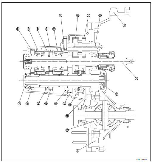
- 3rd input gear
- 3rd-4th synchronizer hub assembly
- 4th input gear
- 5th input gear
- 5th-6th synchronizer hub assembly
- 6th input gear
- Transaxle case
- 6th main gear
- 5th main gear
- 4th main gear
- 3rd main gear
- 2nd main gear
- 1st-2nd synchronizer hub assembly
- 1st main gear
- Differential
- Final gear
- Mainshaft
- Input shaft
- Clutch housing
- Reverse idler shaft
- Reverse input gear
- Reverse output gear
System Description
Triple-cone synchronizer
Triple-cone synchronizers are adopted for the 1st and the 2nd gears to reduce operating force of the shifter lever.
- 1st main gear
- 1st-2nd coupling sleeve
- Insert key
- Outer baulk ring
- 2nd main gear
- Synchronizer cone
- Inner baulk ring
- 1st-2nd synchronizer hub
Reverse gear noise prevention function (synchronizing method)
Reverse gear assembly consists of reverse input gear, return spring, reverse baulk ring, and reverse output gear. When the shifter lever is moved to the reverse position, the construction allows smooth shift operation by stopping the reverse idler shaft rotation by frictional force of synchronizer.
- Reverse fork rod
- Reverse output gear
- Return spring
- Reverse baulk ring
- Reverse input gear
 Preparation
Special Service Tools
The actual shape of the tools may differ from those illustrated here.
Commercial Service Tools
...
 DTC/Circuit diagnosis
POSITION SWITCH
BACK-UP LAMP SWITCH
BACK-UP LAMP SWITCH : Component Inspection
1.CHECK BACK-UP LAMP SWITCH
Disconnect position switch harness connector. Refer to TM-21, "Removal
and In ...
Other materials:
Symptom diagnosis
HEATER AND AIR CONDITIONING SYSTEM
CONTROL SYMPTOMS
Diagnosis Chart By Symptom
Note:
Perform the self-diagnoses with consult before performing the symptom
diagnosis. If dtc is detected, perform
the corresponding diagnosis.
INSUFFICIENT COOLING
Description
Symptom
Insufficient ...
Preparation
Special Service Tools
NOTE:
The actual shapes of Kent-Moore tools may differ from those of special
service tools illustrated here.
Commercial Service Tools
...
P2138 APP Sensor
DTC Logic
DTC DETECTION LOGIC
NOTE:
If DTC P2138 is displayed with DTC P0643, first perform the trouble
diagnosis for DTC P0643. Refer to
EC-353, "DTC Logic".
DTC No.
CONSULT screen terms
(Trouble diagnosis content)
DTC detecting condition
Possible cause
...
