Nissan Sentra Service Manual: System
VDC/TCS/ABS
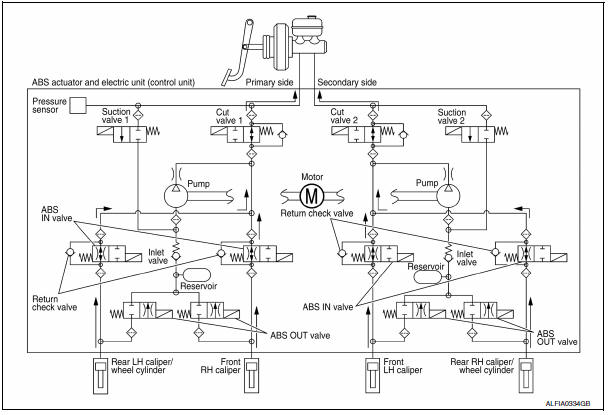
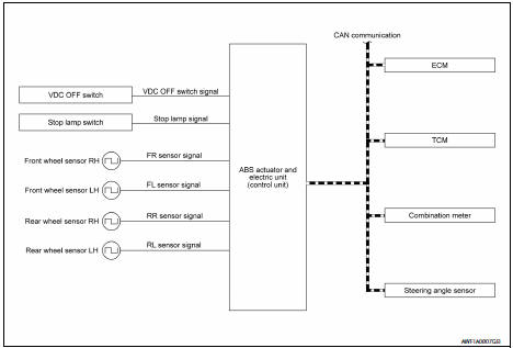
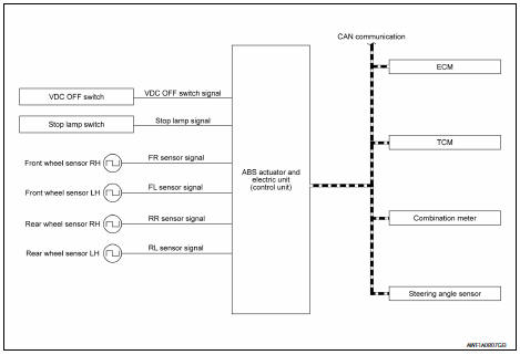
VDC/TCS/ABS : System Diagram
VDC/TCS/ABS : System Description
-
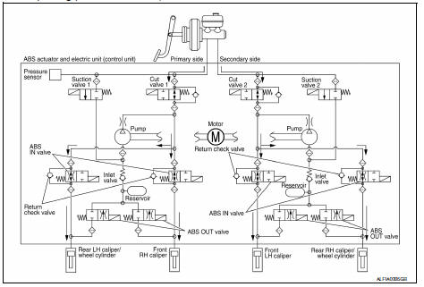
The system switches fluid pressure of each brake caliper and each wheel cylinder to increase, to hold, or to decrease according to signals from control unit in ABS actuator and electric unit (control unit). This control system is applied to VDC, TCS, ABS and EBD functions.
-
Fail-safe function is available for each function and is activated by each function when system malfunction occurs.
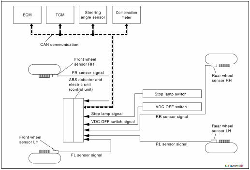
INPUT SIGNAL AND OUTPUT SIGNAL
Major signal transmission between each unit via communication lines is shown in the following table.
| Component | Signal description |
| Steering angle sensor | Transmits the steering angle sensor signal to ABS actuator and electric unit (control unit) via CAN communication. |
| ECM | Transmits the following signals to ABS actuator and electric unit
(control unit) via CAN communication.
|
| TCM | Transmits the current gear position signal to ABS actuator and electric unit (control unit) via CAN communication. |
| Combination meter | Transmits the following signals to ABS actuator and electric unit
(control unit) via CAN communication.
Receives the following signals from ABS actuator and electric unit (control unit) via CAN communication.
|
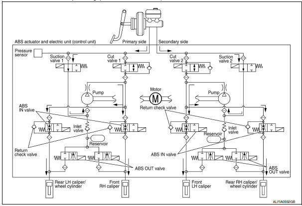
VALVE OPERATION (VDC AND TCS FUNCTIONS)
The control unit built in the ABS actuator and electric unit (control unit) controls fluid pressure of the brake calipers by operating each valve.
VDC and TCS Functions are Operating (Pressure Increases)
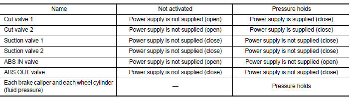
| Name | Not activated | Pressure increases |
| Cut valve 1 | Power supply is not supplied (open) | Power supply is supplied (close) |
| Cut valve 2 | Power supply is not supplied (open) | Power supply is supplied (close) |
| Suction valve 1 | Power supply is not supplied (close) | Power supply is supplied (open) |
| Suction valve 2 | Power supply is not supplied (close) | Power supply is supplied (open) |
| ABS IN valve | Power supply is not supplied (open) | Power supply is not supplied (open) |
| ABS OUT valve | Power supply is not supplied (close) | Power supply is not supplied (close) |
| Each brake caliper and each wheel cylinder (fluid pressure) | — | Pressure increases |
Front RH brake caliper
-
Brake fluid is conveyed to the pump from the master cylinder through suction valve 1 and is pressurized by the pump operation. The pressurized brake fluid is supplied to the front RH brake caliper through the ABS IN valve. For the left caliper, brake fluid pressure is maintained because the pressurization is unnecessary. The pressurization for the left caliper is controlled separately from the right caliper.
Front LH brake caliper
-
Brake fluid is conveyed to the pump from the master cylinder through suction valve 2 and is pressurized by the pump operation. The pressurized brake fluid is supplied to the front LH brake caliper through the ABS IN valve. For the right caliper, brake fluid pressure is maintained because the pressurization is unnecessary.
The pressurization for the right caliper is controlled separately from the left caliper.
Rear RH brake caliper/wheel cylinder
-
Brake fluid is conveyed to the pump from the master cylinder through suction valve 2 and is pressurized by the pump operation. The pressurized brake fluid is supplied to the rear RH brake caliper/wheel cylinder through the ABS IN valve. For the left caliper/wheel cylinder, brake fluid pressure is maintained because the pressurization is unnecessary. The pressurization for the left caliper/wheel cylinder is controlled separately from the right caliper/wheel cylinder.
Rear LH brake caliper/wheel cylinder
-
Brake fluid is conveyed to the pump from the master cylinder through suction valve 1 and is pressurized by the pump operation. The pressurized brake fluid is supplied to the rear LH brake caliper/wheel cylinder through the ABS IN valve. For the right caliper/wheel cylinder, brake fluid pressure is maintained because the pressurization is unnecessary. The pressurization for the right caliper/wheel cylinder is controlled separately from the left caliper/wheel cylinder.
VDC and TCS Functions Start Operating (Pressure Holds)
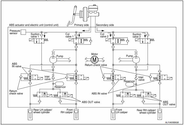
Front RH brake caliper
-
Since the cut valve 1 and the suction valve 1 are closed, the front RH brake caliper, master cylinder, and reservoir are blocked. This maintains fluid pressure applied on the front RH brake caliper. The pressurization for the left caliper is controlled separately from the right caliper.
Front LH brake caliper
-
Since the cut valve 2 and the suction valve 2 are closed, the front LH brake caliper, master cylinder, and reservoir are blocked. This maintains fluid pressure applied on the front LH brake caliper. The pressurization for the right caliper is controlled separately from the left caliper.
Rear RH brake caliper/wheel cylinder
-
Since the cut valve 2 and the suction valve 2 are closed, the rear RH brake caliper/wheel cylinder, master cylinder, and reservoir are blocked. This maintains fluid pressure applied on the rear RH brake caliper/wheel cylinder. The pressurization for the left caliper/wheel cylinder is controlled separately from the right caliper/ wheel cylinder.
Rear LH brake caliper/wheel cylinder
-
Since the cut valve 1 and the suction valve 1 are closed, the rear LH brake caliper/wheel cylinder, master cylinder, and reservoir are blocked. This maintains fluid pressure applied on the rear LH brake caliper/wheel cylinder. The pressurization for the right caliper/wheel cylinder is controlled separately from the left caliper/ wheel cylinder.
VDC and TCS Functions Operating (Pressure Decreases)
Front RH brake caliper
-
Since the suction valve 1 and the ABS OUT valve are closed and the cut valve 1 and the ABS IN valve are open, the fluid pressure applied on the front RH brake caliper is reduced by supplying the fluid pressure to the master cylinder via the ABS IN valve and the cut valve 1. The pressurization for the right caliper is controlled separately from the left caliper.
Front LH brake caliper
-
Since the suction valve 2 and the ABS OUT valve are closed and the cut valve 2 and the ABS IN valve are open, the fluid pressure applied on the front LH brake caliper is reduced by supplying the fluid pressure to the master cylinder via the ABS IN valve and the cut valve 2. The pressurization for the left caliper is controlled separately from the right caliper.
Rear RH brake caliper/wheel cylinder
-
Since the suction valve 2 and the ABS OUT valve are closed and the cut valve 2 and the ABS IN valve are open, the fluid pressure applied on the rear RH brake caliper/wheel cylinder is reduced by supplying the fluid pressure to the master cylinder via the ABS IN valve and the cut valve 2. The pressurization for the right caliper/ wheel cylinder is controlled separately from the left caliper/wheel cylinder.
Rear LH brake caliper/wheel cylinder
-
Since the suction valve 1 and the ABS OUT valve are closed and the cut valve 1 and the ABS IN valve are open, the fluid pressure applied on the rear LH brake caliper/wheel cylinder is reduced by supplying the fluid pressure to the master cylinder via the ABS IN valve and the cut valve 1. The pressurization for the left caliper/ wheel cylinder is controlled separately from the right caliper/wheel cylinder.
Component Parts and Function
| Component | Function |
| Pump | Returns the brake fluid reserved in reservoir to master cylinder by reducing pressure. |
| Motor | Activates the pump according to signals from ABS actuator and electric unit (control unit). |
| Cut valve 1 Cut valve 2 | Shuts off the ordinary brake line from master cylinder. |
| Suction valve 1 Suction valve 2 | Supplies the brake fluid from master cylinder to the pump. |
| ABS IN valve | Switches the fluid pressure line to increase or hold according to signals from control unit. |
| ABS OUT valve | Switches the fluid pressure line to increase, hold or decrease according to signals from control unit. |
| Return check valve | Returns the brake fluid from brake caliper and wheel cylinder to master cylinder by bypassing orifice of each valve when brake is released. |
| Reservoir | Temporarily reserves the brake fluid drained from brake caliper, so that pressure efficiently decreases when decreasing pressure of brake caliper and wheel cylinder |
| Pressure sensor | Detects the brake fluid pressure and transmits signal to ABS actuator and electric unit (control unit). |
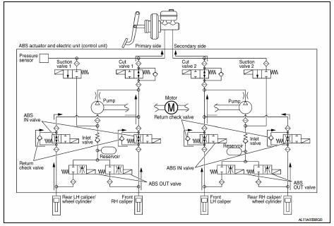
VALVE OPERATION (ABS AND EBD FUNCTIONS)
The control unit built into the ABS actuator and electric unit (control unit) controls fluid pressure of the brake calipers by operating each valve.
Brake Pedal Applied or ABS Function Operating (Pressure Increases)

| Name | Not activated | During pressure increases |
| Cut valve 1 | Power supply is not supplied (open) | Power supply is not supplied (open) |
| Cut valve 2 | Power supply is not supplied (open) | Power supply is not supplied (open) |
| Suction valve 1 | Power supply is not supplied (close) | Power supply is not supplied (close) |
| Suction valve 2 | Power supply is not supplied (close) | Power supply is not supplied (close) |
| ABS IN valve | Power supply is not supplied (open) | Power supply is supplied (close) |
| ABS OUT valve | Power supply is not supplied (close) | Power supply is not supplied (close) |
| Each brake caliper and each wheel cylinder (fluid pressure) |
— |
Pressure increases |
Front RH brake caliper
- When the cut valve 1 and the ABS IN valve opens, brake fluid is supplied to the front RH brake caliper from the master cylinder through the ABS IN valve. Brake fluid does not flow into the reservoir because the ABS OUT valve is closed.
Front LH brake caliper
- When the cut valve 2 and the ABS IN valve opens, brake fluid is supplied to the front LH brake caliper from the master cylinder through the ABS IN valve. Brake fluid does not flow into the reservoir because the ABS OUT valve is closed.
Rear RH brake caliper/wheel cylinder
- When the cut valve 2 and the ABS IN valve opens, brake fluid is supplied to the rear RH brake caliper/wheel cylinder from the master cylinder through the ABS IN valve. Brake fluid does not flow into the reservoir because the ABS OUT valve is closed.
Rear LH brake caliper/wheel cylinder
- When the cut valve 1 and the ABS IN valve opens, brake fluid is supplied to the rear LH brake caliper/wheel cylinder from the master cylinder through the ABS IN valve. Brake fluid does not flow into the reservoir because the ABS OUT valve is closed.
ABS Function Starts Operating (Pressure Holds)
|
Name |
Not activated | During pressure holds |
| Cut valve 1 | Power supply is not supplied (open) | Power supply is not supplied (open) |
| Cut valve 2 | Power supply is not supplied (open) | Power supply is not supplied (open) |
| Suction valve 1 | Power supply is not supplied (close) | Power supply is not supplied (close) |
| Suction valve 2 | Power supply is not supplied (close) | Power supply is not supplied (close) |
| ABS IN valve | Power supply is not supplied (open) | Power supply is supplied (close) |
| ABS OUT valve | Power supply is not supplied (close) | Power supply is not supplied (close) |
| Each brake caliper and each wheel cylinder (fluid pressure) | — | Pressure holds |
Front RH brake caliper
-
Since the ABS IN valve and the ABS OUT valve are closed, the front RH brake caliper, master cylinder, and reservoir are blocked. This maintains fluid pressure applied on the front RH brake caliper.
Front LH brake caliper
-
Since the ABS IN valve and the ABS OUT valve are closed, the front LH brake caliper, master cylinder, and reservoir are blocked. This maintains fluid pressure applied on the front LH brake caliper.
Rear RH brake caliper/wheel cylinder
-
Since the ABS IN valve and the ABS OUT valve are closed, the rear RH brake caliper/wheel cylinder, master cylinder, and reservoir are blocked. This maintains fluid pressure applied on the rear RH brake caliper/wheel cylinder.
Rear LH brake caliper/wheel cylinder
-
Since the ABS IN valve and the ABS OUT valve are closed, the rear LH brake caliper/wheel cylinder, master cylinder, and reservoir are blocked. This maintains fluid pressure applied on the rear LH brake caliper/wheel cylinder.
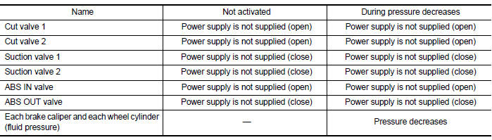
ABS Function Operating (Pressure Decreases)
| Name | Not activated | During pressure decreases |
| Cut valve 1 | Power supply is not supplied (open) | Power supply is not supplied (open) |
| Cut valve 2 | Power supply is not supplied (open) | Power supply is not supplied (open) |
| Suction valve 1 | Power supply is not supplied (close) | Power supply is not supplied (close) |
| Suction valve 2 | Power supply is not supplied (close) | Power supply is not supplied (close) |
| ABS IN valve | Power supply is not supplied (open) | Power supply is supplied (close) |
| ABS OUT valve | Power supply is not supplied (close) | Power supply is supplied (open) |
| Each brake caliper and each wheel cylinder (fluid pressure) |
— |
Pressure decreases |
Front RH brake caliper
-
Since the ABS IN valve is closed and the ABS OUT valve is opened, fluid pressure applied on the front RH brake caliper is supplied to the reservoir through the ABS OUT valve. This fluid pressure decreases when sent to the master cylinder by the pump.
Front LH brake caliper
-
Since the ABS IN valve is closed and the ABS OUT valve is opened, fluid pressure applied on the front LH brake caliper is supplied to the reservoir through the ABS OUT valve. This fluid pressure decreases when sent to the master cylinder by the pump.
Rear RH brake caliper/wheel cylinder
-
Since the ABS IN valve is closed and the ABS OUT valve is opened, fluid pressure applied on the rear RH brake caliper/wheel cylinder is supplied to the reservoir through the ABS OUT valve. This fluid pressure decreases when sent to the master cylinder by the pump.
Rear LH brake caliper/wheel cylinder
-
Since the ABS IN valve is closed and the ABS OUT valve is opened, fluid pressure applied on the rear LH brake caliper/wheel cylinder is supplied to the reservoir through the ABS OUT valve. This fluid pressure decreases when sent to the master cylinder by the pump.
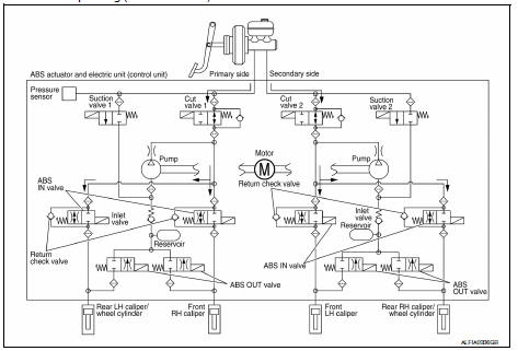
ABS Function Operating (Pressure Increases)
| Name | Not activated | During pressure increases |
| Cut valve 1 | Power supply is not supplied (open) | Power supply is not supplied (open) |
| Cut valve 2 | Power supply is not supplied (open) | Power supply is not supplied (open) |
| Suction valve 1 | Power supply is not supplied (close) | Power supply is not supplied (close) |
| Suction valve 2 | Power supply is not supplied (close) | Power supply is not supplied (close) |
| ABS IN valve | Power supply is not supplied (open) | Power supply is not supplied (open) |
| ABS OUT valve | Power supply is not supplied (close) | Power supply is not supplied (close) |
| Each brake caliper and each wheel cylinder (fluid pressure) |
— |
Pressure increases |
Front RH brake caliper
-
Brake fluid is supplied to the front RH brake caliper from the master cylinder through the cut valve 1 and the ABS IN valve. Since the suction valve 1 and the ABS OUT valve is closed, the fluid does not flow into the reservoir. The amount of brake fluid supplied to the front RH brake caliper from the master cylinder is controlled according to time that the ABS IN valve is not energized (time that the ABS IN valve is open).
Front LH brake caliper
-
Brake fluid is supplied to the front LH brake caliper from the master cylinder through the cut valve 2 and the ABS IN valve. Since the suction valve 2 and the ABS OUT valve is closed, the fluid does not flow into the reservoir. The amount of brake fluid supplied to the front LH brake caliper from the master cylinder is controlled according to time that the ABS IN valve is not energized (time that the ABS IN valve is open).
Rear RH brake caliper/wheel cylinder
-
Brake fluid is supplied to the rear RH brake caliper/wheel cylinder from the master cylinder through the cut valve 2 and the ABS IN valve. Since the suction valve 2 and the ABS OUT valve is closed, the fluid does not flow into the reservoir. The amount of brake fluid supplied to the rear RH brake caliper/wheel cylinder from the master cylinder is controlled according to time that the ABS IN valve is not energized (time that the ABS IN valve is open).
-
Brake fluid is supplied to the rear LH brake caliper/wheel cylinder from the master cylinder through the cut valve 1 and the ABS IN valve. Since the suction valve 1 and the ABS OUT valve is closed, the fluid does not flow into the reservoir. The amount of brake fluid supplied to the rear LH brake caliper/wheel cylinder from the master cylinder is controlled according to time that the ABS IN valve is not energized (time that the ABS IN valve is open).
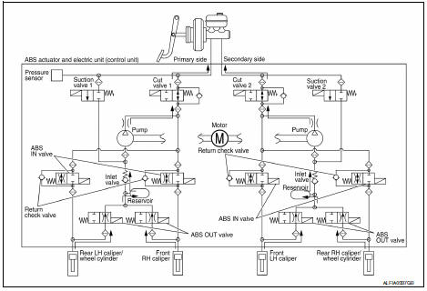
Brake Release
| Name | Not activated | During brake release |
| Cut valve 1 | Power supply is not supplied (open) | Power supply is not supplied (open) |
| Cut valve 2 | Power supply is not supplied (open) | Power supply is not supplied (open) |
| Suction valve 1 | Power supply is not supplied (close) | Power supply is not supplied (close) |
| Suction valve 2 | Power supply is not supplied (close) | Power supply is not supplied (close) |
| ABS IN valve | Power supply is not supplied (open) | Power supply is not supplied (open) |
| ABS OUT valve | Power supply is not supplied (close) | Power supply is not supplied (close) |
| Each brake caliper and each wheel cylinder (fluid pressure) |
— |
Pressure decreases |
Front RH brake caliper
-
Brake fluid is supplied to the front RH brake caliper through the return check valve of the ABS IN valve and the cut valve 1, and returns to the master cylinder.
Front LH brake caliper
-
Brake fluid is supplied to the front LH brake caliper through the return check valve of the ABS IN valve and the cut valve 2, and returns to the master cylinder.
Rear RH brake caliper/wheel cylinder
-
Brake fluid is supplied to the rear RH brake caliper/wheel cylinder through the return check valve of the ABS IN valve and the cut valve 2, and returns to the master cylinder.
Rear LH brake caliper/wheel cylinder
-
Brake fluid is supplied to the rear LH brake caliper/wheel cylinder through the return check valve of the ABS IN valve and the cut valve 1, and returns to the master cylinder.
Component Parts and Function
| Component | Function |
| Pump | Returns the brake fluid reserved in reservoir to master cylinder by reducing pressure. |
| Motor | Activates the pump according to signals from ABS actuator and electric unit (control unit). |
| Cut valve 1 Cut valve 2 | Shuts off the ordinary brake line from master cylinder. |
| Suction valve 1 Suction valve 2 | Supplies the brake fluid from master cylinder to the pump. |
| ABS IN valve | Switches the fluid pressure line to increase or hold according to signals from control unit. |
| ABS OUT valve | Switches the fluid pressure line to increase, hold or decrease according to signals from control unit. |
| Return check valve | Returns the brake fluid from brake caliper and wheel cylinder to master cylinder by bypassing orifice of each valve when brake is released. |
| Reservoir | Temporarily reserves the brake fluid drained from brake caliper, so that pressure efficiently decreases when decreasing pressure of brake caliper and wheel cylinder. |
| Pressure sensor | Detects the brake fluid pressure and transmits signal to ABS actuator and electric unit (control unit). |
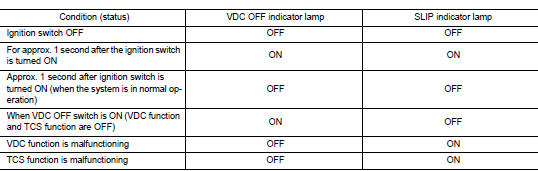
Conditions for indicator lamp illumination
-
Turns ON when VDC and TCS functions are switched to non-operational status (OFF) by VDC OFF switch.
-
Turns ON when ignition switch turns ON and turns OFF when the system is normal, for bulb check purposes.
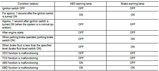
Conditions for warning lamp illumination
Turns ON when ignition switch turns ON and turns OFF when the system is normal, for bulb check purposes.
VDC/TCS/ABS : VDC Function
SYSTEM DIAGRAM
SYSTEM DESCRIPTION
-
Side slip or tail slip may occur while driving on a slippery road or intending an urgent evasive driving maneuver.
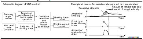
VDC function detects side slip status using each sensor when side slip or tail slip is about to occur and improves vehicle stability by brake control and engine output control during driving.
-
In addition to ABS function, EBD function and TCS function, target side slip amount is calculated according to steering operation amount from steering angle sensor. By comparing this information with vehicle side slip amount that is calculated from information from yaw rate/side G sensor and wheel sensor, vehicle driving conditions (conditions of understeer or oversteer) are judged and vehicle stability is improved by brake force control on all 4 wheels and engine output control.
-
VDC function can be switched to non-operational status (OFF) by operating VDC OFF switch. In this case, VDC OFF indicator lamp turns ON.
-
Control unit portion automatically improves driving stability by performing brake force control as well as engine output control, by transmitting drive signal to actuator portion according to difference between target side slip amount and vehicle side slip amount
-
Brake force control function at braking hard detects driver′s brake operations with the pressure sensor, judges a brake booster′s maximum brake power function by using information from the vacuum sensor, and enhances more powerful braking force by controlling brakes of four wheels.
-
VDC warning lamp blinks while VDC function is in operation and indicates to the driver that the function is in operation.
-
CONSULT can be used to diagnose the system.
-
Fail-safe function is adopted. When a malfunction occurs in VDC function, the control is suspended for VDC function and TCS function. However, ABS function and EBD function operate normally. Refer to BRC-39, "Fail-safe".
INPUT SIGNAL AND OUTPUT SIGNAL
Major signal transmission between each unit via communication lines is shown in the following table.
| Component | Signal description |
| ECM | Transmits the following signals to ABS actuator and electric unit
(control unit) via CAN communication.
|
| TCM | Transmits the current gear position signal to ABS actuator and electric unit (control unit) via CAN communication. |
| Steering angle sensor | Transmits the steering angle sensor signal to ABS actuator and electric unit (control unit) via CAN communication. |
| Combination meter | Transmits the following signals to ABS actuator and electric unit
(control unit) via CAN communication.
Receives the following signals from ABS actuator and electric unit (control unit) via CAN communication.
|
OPERATION CHARACTERISTICS
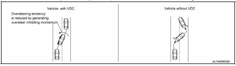
VDC Function That Prevents Oversteer Tendency
-
During cornering, brake force (brake fluid pressure) is applied on front wheel and rear wheel on the outer side of turn. Momentum is generated directing the vehicle toward the outer side of the turn. Oversteer is prevented.
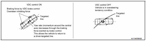
-
Changing driving lane on a slippery road, when there may be a tendency to oversteer, engine output is controlled as well as brake force (brake fluid pressure) of 4 wheels. Oversteer tendency decreases.
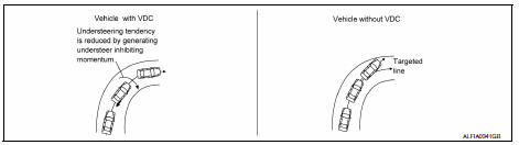
VDC Function That Prevents Understeer Tendency
-
During cornering, brake force (brake fluid pressure) is applied on front wheel and rear wheel on the inner side of turn. Momentum is generated directing the vehicle toward the inner side of the turn. Understeer is prevented.
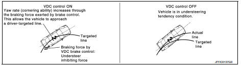
-
Applying brakes during cornering on a slippery road, when there may be a tendency to understeer, engine output is controlled as well as brake force (brake fluid pressure) of 4 wheels. Understeer tendency decreases.
VDC/TCS/ABS : TCS Function
SYSTEM DIAGRAM
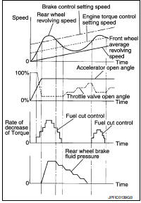
SYSTEM DESCRIPTION
-
Wheel spin status of drive wheel is detected by wheel sensor of 4 wheels. Engine output and transmission shift status is controlled so that slip rate of drive wheels is in appropriate level. When wheel spin occurs on drive wheel, ABS actuator and electric unit (control unit) perform brake force control of LH and RH drive wheels (apply brake force by increasing brake fluid pressure of drive wheel) and decrease engine torque by engine torque control. Wheel spin amount decreases. Engine torque is controlled to appropriate level.
-
TCS function can be switched to non-operational status (OFF) by operating VDC OFF switch. In this case, VDC OFF indicator lamp turns ON.
-
SLIP indicator lamp blinks while TCS function is in operation and indicates to the driver that the function is in operation.
-
CONSULT can be used to diagnose the system.
-
Fail-safe function is adopted. When a malfunction occurs in TCS function, the control is suspended for VDC function and TCS function.
However, ABS function and EBD function operate normally.
Refer to BRC-39, "Fail-safe".
INPUT SIGNAL AND OUTPUT SIGNAL
Major signal transmission between each unit via communication lines is shown in the following table.
| Component | Signal description |
| ECM | Transmits the following signals to ABS actuator and electric unit
(control unit) via CAN communication.
|
| TCM | Transmits the current gear position signal to ABS actuator and electric unit (control unit) via CAN communication. |
| Steering angle sensor | Transmits the steering angle sensor signal to ABS actuator and electric unit (control unit) via CAN communication. |
| Combination meter | Transmits the following signals to ABS actuator and electric unit
(control unit) via CAN communication.
Receives the following signals from ABS actuator and electric unit (control unit) via CAN communication.
|
VDC/TCS/ABS : ABS Function
SYSTEM DIAGRAM
-
By preventing wheel lock through brake force (brake fluid pressure) control that is electronically controlled by detecting wheel speed during braking, stability during emergency braking is improved so that obstacles can be easily bypassed by steering operation.
-
During braking, control units calculate wheel speeds, and transmit pressure increase, hold or decrease signals to actuator portion according to wheel slip status.
-
The following effects are obtained by preventing wheel lock during braking.
-
Vehicle tail slip is prevented during braking when driving straight.
-
Understeer and oversteer tendencies are moderated during braking while cornering.
-
Obstacles may be easily bypassed by steering operation during braking.
-
CONSULT can be used to diagnose the system.
-
Fail-safe function is adopted. When a malfunction occurs in ABS function, the control is suspended for VDC function, TCS function and ABS function. However, EBD function operates normally.
Refer to BRC-28, "VDC/TCS/ABS : Fail-safe".
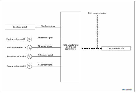
INPUT SIGNAL AND OUTPUT SIGNAL
Major signal transmission between each unit via communication lines is shown in the following table.
| Component | Signal description |
| Combination meter | Receives the following signals from ABS actuator and electric unit
(control unit) via CAN communication.
|
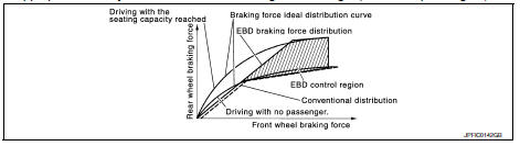
VDC/TCS/ABS : EBD Function
SYSTEM DIAGRAM
-
By preventing rear wheel slip increase through rear wheel brake force (brake fluid pressure) control that is electronically controlled when slight skip on front and rear wheels are detected during braking, stability during braking is improved.
-
EBD function is expanded and developed from conventional ABS function and corrects rear wheel brake force to appropriate level by electronic control according to load weight (number of passengers).
-
During braking, control unit portion compares slight slip on front and rear wheels by wheel sensor signal, transmits drive signal to actuator portion when rear wheel slip exceeds front wheel slip for the specified value or more, and controls rear wheel brake force (brake fluid pressure) so that increase of rear wheel slip is prevented and slips on front wheel and rear wheel are nearly equalized.
ABS control is applied when slip on each wheel increases and wheel speed is the threshold value of ABS control or less.
-
CONSULT can be used to diagnose the system.
-
Fail-safe function is adopted. When a malfunction occurs in EBD function, the control is suspended for VDC function, TCS function, ABS function and EBD function. Refer to BRC-28, "VDC/TCS/ABS : Fail-safe".
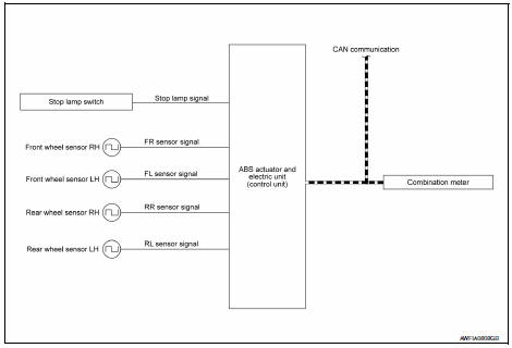
INPUT SIGNAL AND OUTPUT SIGNAL
Major signal transmission between each unit via communication lines is shown in the following table.
| Component | Signal description |
| Combination meter | Receives the following signals from ABS actuator and electric unit
(control unit) via CAN communication.
|
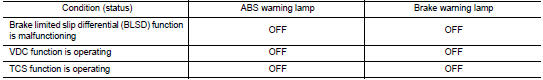
VDC/TCS/ABS : Fail-safe
VDC AND TCS FUNCTIONS
VDC warning lamp in combination meter turns ON when a malfunction occurs in system [ABS actuator and electric unit (control unit)]. The control is suspended for VDC and TCS functions. However, ABS and EBD functions operate normally.
ABS FUNCTION
ABS warning lamp and SLIP indicator lamp in combination meter turn ON when a malfunction occurs in system [ABS actuator and electric unit (control unit)]. The control is suspended for VDC, TCS and ABS functions.
However, EBD functions operate normally.
EBD FUNCTION
ABS warning lamp, brake warning lamp and SLIP indicator lamp in combination meter turn ON when a malfunction occurs in system [ABS actuator and electric unit (control unit)]. The control is suspended for VDC, TCS, ABS and EBD functions
| DTC | Malfunction detected condition | Fail-safe condition |
| C1101 | When an open circuit is detected in rear RH wheel sensor circuit. | The following functions are suspended:
|
| C1102 | When an open circuit is detected in rear LH wheel sensor circuit. | |
| C1103 | When an open circuit is detected in front RH wheel sensor circuit. | |
| C1104 | When an open circuit is detected in front LH wheel sensor circuit. | |
| C1105 |
|
|
| C1106 |
|
|
| C1107 |
|
|
| C1108 |
|
|
| C1109 |
|
The following functions are suspended:
|
| C1110 | When there is an internal malfunction in the ABS actuator and electric unit (control unit). | |
| C1111 | When a malfunction is detected in motor or motor relay. | The following functions are suspended:
|
| C1113 | When a malfunction is detected in longitudinal G signal. | The following functions are suspended:
|
| C1115 | When difference in wheel speed between any wheel and others is detected when the vehicle is driven, because of installation of tires other than specified. | The following functions are suspended:
|
| DTC | Malfunction detected condition | Fail-safe condition |
| C1116 | When stop lamp switch signal is not input when brake pedal operates. | The following functions are suspended:
|
| C1120 | When a malfunction is detected in front LH ABS IN valve. | The following functions are suspended:
|
| C1121 | When a malfunction is detected in front LH ABS OUT valve. | |
| C1122 | When a malfunction is detected in front RH ABS IN valve. | |
| C1123 | When a malfunction is detected in front RH ABS OUT valve. | |
| C1124 | When a malfunction is detected in rear LH ABS IN valve. | |
| C1125 | When a malfunction is detected in rear LH ABS OUT valve. | |
| C1126 | When a malfunction is detected in rear RH ABS IN valve. | |
| C1127 | When a malfunction is detected in rear RH ABS OUT valve. | |
| C1130 | When a malfunction is detected in ECM system. | The following functions are suspended:
|
| C1140 | When a malfunction is detected in actuator relay. | The following functions are suspended:
|
| C1142 | When a malfunction is detected in VDC pressure sensor. | The following functions are suspended:
|
| C1143 | When a malfunction is detected in steering angle sensor. | |
| C1144 | When neutral position adjustment of steering angle sensor is not complete. | |
| C1145 | When a malfunction is detected in yaw rate signal, or signal line of yaw rate/side/ decel G sensor is open or shorted. | |
| C1146 | When a malfunction is detected in side G signal, or signal line of yaw rate/side/decel G sensor is open or shorted. | |
| C1155 | When brake fluid level low signal is detected. | The following functions are suspended:
|
| C1164 | When a malfunction is detected in cut valve 1. | The following functions are suspended:
|
| C1165 | When a malfunction is detected in cut valve 2. | |
| C1166 | When a malfunction is detected in suction valve 1. | |
| C1167 | When a malfunction is detected in suction valve 2. | |
| C1170 | When the information in ABS actuator and electric unit (control unit) is not the same. | The following functions are suspended:
|
| U1000 | When CAN communication signal is not continuously transmitted or received for 2 seconds or more. | The following functions are suspended:
|
| U1002 | When ABS actuator and electric unit (control unit) is not transmitting or receiving CAN communication signal for 2 seconds or less. | |
| U1010 | When detecting error during the initial diagnosis of CAN controller of ABS actuator and electric unit (control unit). |
 Component parts
Component Parts Location
ABS actuator and electric unit (control
unit)
IPDM E/R
Brake fluid level switch
Front wheel sensor LH (RH similar)
Rear wheel sensor LH (RH s ...
 Diagnosis system [abs actuator and electric unit (control
unit)]
Diagnosis system [abs actuator and electric unit (control
unit)]
CONSULT Function (ABS)
FUNCTION
CONSULT can display each diagnostic item using the following
direct diagnostic modes.
Direct Diagnostic Mode
Description
ECU identification
T ...
Other materials:
Precaution for Work
When removing or disassembling each component, be careful not to damage
or deform it. If a component
may be subject to interference, be sure to protect it with a shop cloth.
When removing (disengaging) components with a screwdriver or similar
tool, be sure to wrap the component
with a ...
Control buttons
The control buttons for the Bluetooth® Hands-
Free Phone System are located on the steering
wheel.
PHONE/SEND
Press the button to initiate
a VR session or answer an incoming
call.
You can also use the button
to interrupt the system feedback
and give a command at once. See
“List of ...
USB interface (models without Navigation System) (if so equipped)
Connecting a device to the USB input
jack
WARNINGDo not connect, disconnect, or operate the
USB device while driving. Doing so can be
a distraction. If distracted you could lose
control of your vehicle and cause an accident
or serious injury.
CAUTION
Do not force t ...
