Nissan Sentra Service Manual: Component parts
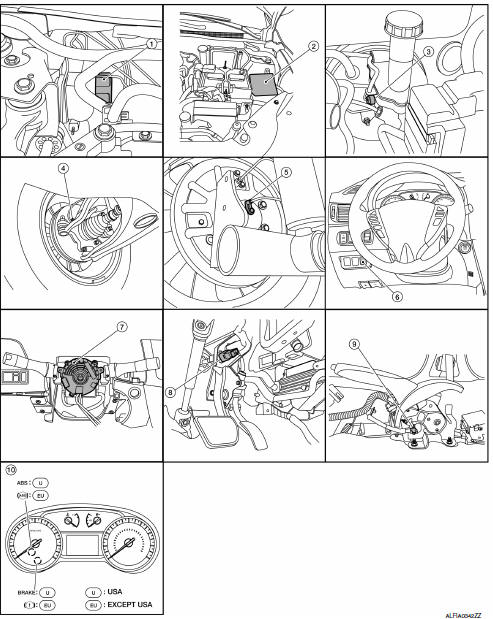
Component Parts Location
-
ABS actuator and electric unit (control unit)
-
IPDM E/R
-
Brake fluid level switch
-
Front wheel sensor LH (RH similar)
-
Rear wheel sensor LH (RH similar)
-
VDC OFF switch
-
Steering angle sensor (view with steering wheel removed)
-
Stop lamp switch
-
Parking brake switch
-
Combination meter
Component Description
ABS Actuator and Electric Unit (Control Unit)
Electric unit (control unit) is integrated with actuator and comprehensively controls VDC function, TCS function, ABS function and EBD function.
ELECTRIC UNIT (CONTROL UNIT)
-
Brake fluid pressure is controlled according to signals from each sensor.
-
If malfunction is detected, the system enters fail-safe mode.
ACTUATOR
The following components are integrated with ABS actuator.
Pump
Returns the brake fluid reserved in reservoir to master cylinder by reducing pressure
Motor
Activates the pump according to signals from ABS actuator and electric unit (control unit).
Motor Relay
Operates the motor ON/OFF according to signals from ABS actuator and electric unit (control unit).
Actuator Relay (Main Relay)
Operates each valve ON/OFF according to signals from ABS actuator and electric unit (control unit).
ABS IN Valve
Switches the fluid pressure line to increase or hold according to signals from control unit.
ABS OUT Valve
Switches the fluid pressure line to increase, hold or decrease according to signals from control unit.
Cut Valve 1, Cut Valve 2
Shuts off the ordinary brake line from master cylinder, when VDC function and TCS function are activated.
Suction Valve 1, Suction Valve 2
Supplies the brake fluid from master cylinder to the pump, when VDC function and TCS function are activated.
Return Check Valve
Returns the brake fluid from brake caliper and wheel cylinder to master cylinder by bypassing orifice of each valve when brake is released.
Reservoir
Temporarily reserves the brake fluid drained from brake caliper, so that pressure efficiently decreases when decreasing pressure of brake caliper and wheel cylinder.
Yaw rate/side/decel G sensor
Calculates the following information that affects the vehicle.
-
Vehicle rotation angular velocity (yaw rate signal)
-
Vehicle lateral acceleration (side G signal) and longitudinal acceleration (decel G signal)
Pressure Sensor
Detects the brake fluid pressure.
Wheel Sensor and Sensor Rotor
NOTE:
-
Wheel sensor of front wheel is installed on steering knuckle.
-
Sensor rotor of front wheel is integrated in wheel hub assembly.
-
Wheel sensor of rear wheel is installed on back plate of rear brake.
-
Sensor rotor of rear wheel is installed on rear brake drum.
-
Never measure resistance and voltage value using a tester because sensor is active sensor.
-
Downsize and weight reduction is aimed. IC for detection portion and magnet for sensor rotor are adopted.
-
Power supply is supplied to detection portion so that magnetic field line is read. Magnetic field that is detected is converted to current signal.
-
When sensor rotor rotates, magnetic field changes. Magnetic field change is converted to current signals (rectangular wave) and is transmitted to ABS actuator and electric unit (control unit). Change of magnetic field is proportional to wheel speed.
Stop Lamp Switch
Detects the operation status of brake pedal and transmits converted electric signal to ABS actuator and electric unit (control unit).
Steering Angle Sensor
Detects the following information and transmits steering angle signal to ABS actuator and electric unit (control unit) via CAN communication.
-
Steering wheel rotation amount
-
Steering wheel rotation angular velocity
-
Steering wheel rotation direction
Brake Fluid Level Switch
Detects the brake fluid level in reservoir tank and transmits converted electric signal from combination meter to ABS actuator and electric unit (control unit) via CAN communication.
Parking Brake Switch
Detects the operation status of parking brake switch and transmits converted electric signal from combination meter to ABS actuator and electric unit (control unit) via CAN communication.
VDC OFF Switch
-
Non-operational status or standby status of VDC and TCS functions can be selected using VDC OFF switch.
VDC OFF indicator lamp indicates the operation status of function. (ON: Non-operational status, OFF: Standby status)
-
VDC OFF indicator lamp turns OFF (standby status) when the engine is started again after it is stopped once while VDC OFF indicator lamp is ON (non-operational status).

 System
VDC/TCS/ABS
VDC/TCS/ABS : System Diagram
VDC/TCS/ABS : System Description
The system switches fluid pressure of each brake caliper and
each wheel cylinder to increase, to hold, or to
...
Other materials:
NISSAN vehicle immobilizer system (if so equipped)
The NISSAN Vehicle Immobilizer System will not
allow the engine to start without the use of a
registered key.
If the engine fails to start using a registered key
(for example, when interference is caused by
another registered key, an automated toll road
device or automatic payment device on ...
System description
Component parts
Body control system
BODY CONTROL SYSTEM : Component Parts Location
Bcm (view with instrument panel removed)
Combination switch reading system
COMBINATION SWITCH READING SYSTEM : Component Parts Location
BCM (view with combination meter
removed)
Combination s ...
Map lamp
Removal and installation
Removal
Lower front edge of map lamp (1) down from the headlining by
releasing the metal clips, then slide forward to clear pawls at
rear.
: Metal clip
Pawl
Disconnect the harness connectors from the map lamp and remove.
Installation
Installation is in t ...
