Nissan Sentra Service Manual: System
Tire pressure monitoring system
TIRE PRESSURE MONITORING SYSTEM : System Diagram
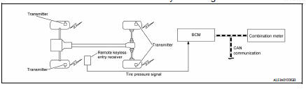
TIRE PRESSURE MONITORING SYSTEM : System Description
- The BCM has pressure judgment and trouble diagnosis functions. When the BCM detects low inflation pressure or another unusual symptom, the low tire pressure warning lamp in the combination meter is illuminated.
- If the tire pressure is less than the specified value, the low tire pressure warning lamp illuminates.
- The TPMS (Tire Pressure Monitoring System) is activated when vehicle speed is 40 km/h (25 MPH) or more.
INPUT/OUTPUT SIGNAL
| Component | Signal Description |
| BCM | Transmits the low tire pressure warning lamp signal via CAN communication to combination meter. |
| Combination meter | Transmits the vehicle speed signal via CAN communication to BCM. |
LOW TIRE PRESSURE WARNING LAMP CONTROL CONDITION
The BCM uses CAN communication to illuminate the low tire pressure warning lamp in the combination meter.
| Condition | Low tire pressure warning lamp |
| Ignition switch OFF | OFF |
| Ignition switch ON (system normal) | Warning light turns on for 1second, then turns off. |
| Low tire pressure | ON |
| Transmitter ID not registered in BCM. | |
| Tire pressure monitoring system malfunction | Warning light blinks 1 minute, then turns on. |
| Tire pressure sensor is in OFF state | Blink (Blinking pattern depends on the positions of nonoperational tire pressure sensors.) |
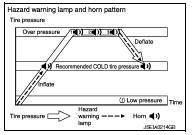
TIRE PRESSURE MONITORING SYSTEM : Easy Fill Tire Alert Function
NOTE:
When beginning tire inflation, it takes a few seconds for the Easy fill tire alert to function. If there is no response for approximately 15 seconds or more, cancel the Easy fill tire alert function and move the vehicle approximately 1 m (3.2 ft) backward or forward to try again.
- The Easy fill tire alert function operates only when the select lever position is in P-range with the ignition switch ON.
- This function informs the driver with a visual and audible indication that the recommended COLD tire pressure has been reached.
- The hazard warning lamps blink when the recommended COLD tire pressure has been reached. After the recommended COLD tire pressure has been reached, the horn sounds once and the hazard warning lamps stop blinking.
- If the tire pressure value is equal to or greater than 30 kPa (0.31 kg/cm2, 4 psi) more than the recommended COLD tire pressure, the hazard warning lamps flash and horn sounds three times.
- To return the tire to the recommended COLD tire pressure, deflate the tire until the horn sounds once and the hazard warning lamps stop blinking.
 Component parts
Component Parts Location
BCM (view with instrument panel removed)
Remote keyless entry receiver (view
with instrument panel removed)
Transmitter
Combination meter
Component Descript ...
 Diagnosis system (BCM) (with intelligent key system)
Common item
COMMON ITEM : CONSULT Function (BCM - COMMON ITEM)
APPLICATION ITEM
CONSULT performs the following functions via CAN communication with BCM.
Direct Diagnostic Mode
Descriptio ...
Other materials:
Periodic maintenance
REAR WHEEL HUB
Inspection
COMPONENT PART
Check the mounting conditions (looseness, back lash) of each component and
component conditions (wear,
damage) are normal.
WHEEL HUB ASSEMBLY (BEARING-INTEGRATED TYPE)
Check the following items, and replace the part it necessary.
Move wheel hub as ...
Oil pan
Exploded View
O-ring
Oil pan (upper)
Oil level gauge guide
O-ring
Oil level gauge
Oil pump drive chain
Crankshaft sprocket
Oil pump sprocket
Oil pump chain tensioner
Oil pump
Drain plug
Drain plug washer
Oil pan (lower)
Oil filter
Clamp
Water hose
Oil cooler
...
Fuel pressure
Work Procedure
FUEL PRESSURE RELEASE
1.FUEL PRESSURE RELEASE
With CONSULT
Turn ignition switch ON.
Perform “FUEL PRESSURE RELEASE” in “WORK SUPPORT” mode of “ENGINE” using
CONSULT
Start engine.
After engine stalls, crank it two or three times to release ...
