Nissan Sentra Service Manual: Oil pan
Exploded View
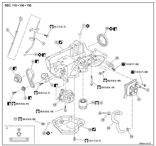
- O-ring
- Oil pan (upper)
- Oil level gauge guide
- O-ring
- Oil level gauge
- Oil pump drive chain
- Crankshaft sprocket
- Oil pump sprocket
- Oil pump chain tensioner
- Oil pump
- Drain plug
- Drain plug washer
- Oil pan (lower)
- Oil filter
- Clamp
- Water hose
- Oil cooler
- Crankshaft position sensor
- Rear oil seal
- Refer to LU-10
- To thermostat housing
- To thermostat housing (M/T models) To CVT oil warmer (CVT models)
- Oil pan side
Removal and Installation (Lower Oil Pan)
REMOVAL
- Drain engine oil. Refer to LU-8, "Draining".
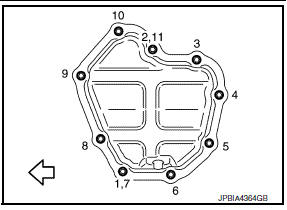
- Remove oil pan (lower) bolts in reverse order as shown.
NOTE:
Disregard the numerical order No.7 and 11 in removal.
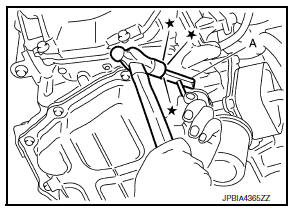
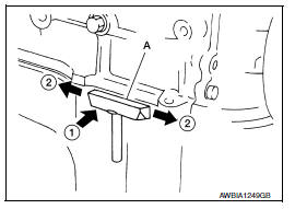
- Insert Tool between oil pan (upper) and oil pan (lower).
CAUTION:
- Do not damage the mating surface.
- Do not insert a screwdriver. This damages the mating surfaces.
- Slide Tool by tapping on the side of Tool (A) using a plastic hammer.
Tool number : KV10111100 (J-37228)
- Remove oil pan (lower).
INSTALLATION
CAUTION:
Do not reuse O-rings or washers.
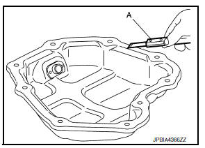
- Install oil pan (lower) as follows:
- Use a suitable tool (A) to remove old liquid gasket from mating surfaces.
- Also remove old liquid gasket from mating surface of oil pan (upper).
- Remove old liquid gasket from the bolt holes and threads.
CAUTION:
Do not scratch or damage the mating surface when cleaning off old liquid gasket.
- Apply a continuous bead of liquid gasket (A) using suitable tool as shown as shown.
(1) : Oil pan (lower)
(b) : 7.5-9.5mm (0.295 - 0.374 in)
(c) : 4.0 - 5.0 mm (0.157 - 0.197 in)
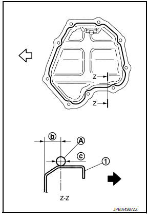
Use Genuine Silicone RTV Sealant, or equivalent. Refer to GI-21, "Recommended Chemical Products and Sealants".
CAUTION:
- Installation should be done within 5 minutes after applying liquid gasket.
- Do not fill the engine with oil for at least 30 minutes after the components are installed to allow the sealant to cure.
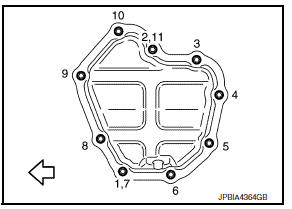
- Tighten bolts in numerical order as shown.
NOTE:
- Tighten bolts the No.1 and 2 in two steps.
- The numerical order No.7 and 11 shows the second steps.
- Install oil pan drain plug.
CAUTION:
- Do not reuse drain plug washer.
- Refer to exploded view installation direction of drain plug washer. Refer to EM-33, "Exploded View".
- Refill the engine with engine oil. Refer to LU-9, "Refilling".
Inspection
INSPECTION AFTER REMOVAL
Clean oil strainer if any object attached.
INSPECTION AFTER INSTALLATION
- Check the engine oil level and adjust engine oil. Refer to LU-7, "Inspection".
- Start engine, and check for leaks of engine oil.
- Stop engine and wait for 10 minutes.
- Check the engine oil level again. Refer to LU-7, "Inspection".
Removal and Installation (Upper Oil Pan)
REMOVAL
- Remove the engine and transaxle assembly. Refer to EM-82, "M/T : Exploded View" (M/T) or EM-86, "CVT : Exploded View" (CVT).
- Remove the clutch cover and clutch disc. Refer to CL-17, "Exploded View".
- Remove the flywheel (M/T) or drive plate (CVT). Refer to EM-90, "Exploded View" (M/T) or EM-92, "Exploded View" (CVT).
- Mount the engine on an engine stand. Refer to EM-72, "Removal and Installation".
- Remove the generator and generator bracket. Refer to CHG-29, "Exploded View".
- Remove oil pan (lower). Refer to EM-33, "Removal and Installation (Lower Oil Pan)".
- Remove oil filter. Refer to LU-10, "Removal and Installation".
- Remove timing chain. Refer to EM-48, "Exploded View".
- Remove oil level gauge and oil level gauge guide.
- Remove oil pump if necessary. Refer to LU-12, "Exploded View".
NOTE:
The oil pan (upper) can be removed and installed without removing the oil pump.
- Remove oil pan (upper) with the following procedure:
- Loosen bolts in reverse order as shown.
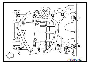
- Using suitable tool as shown by the arrow ( ) open up a crack between oil pan (upper) and cylinder block.
CAUTION:
Do not use suitable tool anywhere other than shown, sealant used is more adhesive than previous types when shipped.
- Insert Tool (A) between oil pan (upper) and cylinder block.
Tool Number : KV10111100 (J-37228)
CAUTION:
Do not damage the mating surface.
- In areas where the cutter is difficult to use, use a plastic hammer to lightly tap (1) the cutter where the liquid gasket is applied. Use a plastic hammer to slide (2) the cutter by tapping on the side.
- Remove O-ring between cylinder block and oil pan (upper).
INSTALLATION
CAUTION:
Do not reuse O-rings or washers.
- Install oil pan (upper) with the following procedure:
- Use a suitable tool (A) to remove old liquid gasket from mating surfaces.
- Remove the old liquid gasket from mating surface of cylinder block.
- Remove old liquid gasket from the bolt holes and threads.
CAUTION:
Do not scratch or damage the mating surfaces when cleaning off old liquid gasket.
- Apply a continuous bead of liquid gasket (D) using suitable tool as shown.
(1) : Oil pan (upper)
(A) : 2 mm (0.08 in) protruded to outside
(B) : 2 mm (0.08 in) protruded to rear oil seal mounting side
(c) : 5.5 - 7.5 mm (0.217 - 0.295 in)
(e) : 4.0 - 5.0 mm (0.157 - 0.197 in)
Use Genuine Silicone RTV Sealant, or equivalent. Refer to GI-21, "Recommended Chemical Products and Sealants".
CAUTION:
- Installation should be done with 5 minutes after applying liquid gasket.
- Do not fill the engine with oil for at least 30 minutes after the components are installed to allow the sealant to cure.
NOTE:
Apply liquid gasket to the outside of bolt holes show by
 mark
mark
- Install new O-ring at cylinder block side.
CAUTION:
- Install avoiding misalignment of O-ring.
- Do not reuse O-ring.
- Tighten bolts in numerical order as shown.
- Install rear oil seal with the following procedure
CAUTION:
- The installation of rear oil seal should be completed within 5 minutes after installing oil pan (upper).
- Always replace rear oil seal with new one.
- Do not touch oil seal lip.
- Do not reuse rear oil seal.
- Wipe off liquid gasket protruding to the rear oil seal mounting part of oil pan (upper) and cylinder block using suitable tool.
- Apply engine oil to entire outside area of rear oil seal.
- Press-fit the rear oil seal using a suitable drift (A) with outer diameter 115 mm (4.53 in) and inner diameter 90 mm (3.54 in).
- Press-fit to the specified dimensions as shown.
(1) : Rear oil seal
(A) : Cylinder block rear end surface
CAUTION:
- Do not touch the grease applied to the oil seal lip.
- Be careful not to damage the rear oil seal mounting part of oil pan (upper) and cylinder block or the crankshaft.
- Press-fit straight, checking that rear oil seal does not curl or tilt.
NOTE:
The standard surface of the dimension is the rear end surface of cylinder block.
- Installation of remaining components is in the reverse order of removal.
INSPECTION AFTER INSTALLATION
- Before starting engine, check oil/fluid levels including engine coolant and engine oil. If there is less than required quantity, fill to the specified level. Refer to MA-11, "Fluids and Lubricants".
- Use procedure below to check for fuel leakage.
- Turn ignition switch ON (with engine stopped). With fuel pressure applied to fuel piping, check for fuel leakage at connection points.
- Start engine. With engine speed increased, check again for fuel leakage at connection points.
- Run engine to check for unusual noise and vibration.
NOTE:
If hydraulic pressure inside timing chain tensioner drops after removal and installation, slack in the guide may generate a pounding noise during and just after engine start. However, this is normal. Noise will stop after hydraulic pressure rises.
- Warm up engine thoroughly to make sure there is no leakage of fuel, exhaust gas, or any oils/fluids including engine oil and engine coolant.
- Bleed air from passages in lines and hoses, such as in cooling system.
- After cooling down engine, again check oil/fluid levels including engine oil and engine coolant. Refill to specified level, if necessary.
- Summary of the inspection items:
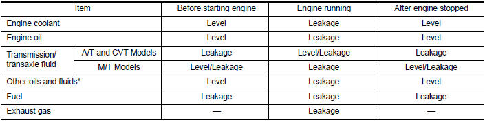
*Power steering fluid, brake fluid, etc.
Inspection
INSPECTION AFTER REMOVAL
Clean oil strainer portion (part of the oil pump) if any object attached.
 Exhaust manifold
Exploded View
CALIFORNIA
Air fuel ratio sensor
Exhaust manifold heat shield (upper)
Exhaust manifold and three way catalyst
Exhaust manifold heat shield (rear)
Exhaust manifold heat ...
 Fuel injector and fuel tube
Exploded View
Bracket
Fuel tube bracket
Fuel feed tube
Quick connector cap
Fuel tube
O-ring (black)
Fuel injector
O-ring (green)
Injector clip
CAUTION:
Do not remove or dis ...
Other materials:
C1101, C1102, C1103, C1104 Wheel sensor
Description
When the sensor rotor rotates, the magnetic field changes. It
converts the magnetic field changes to current
signals (rectangular wave) and transmits them to the ABS actuator and electric
unit (control unit).
DTC Logic
DTC DETECTION LOGIC
DTC
Display Item
Malfuncti ...
Power supply and ground circuit
Combination meter
COMBINATION METER : Diagnosis Procedure
Regarding Wiring Diagram information, refer to MWI-28, "Wiring Diagram".
1.Check fuses
Check that the following fuses are not blown.
Is the fuse blown?
Yes >> replace the blown fuse after repairing the affected circu ...
OIL PAN
Exploded View
Transaxle assembly
Oil pan gasket
Magnet
Oil pan
Overflow tube
Drain plug gasket
Drain plug
Oil pan fitting bolt
: Always replace after every
disassembly.
: NВ·m (kg-m, ft-lb)
: NВ·m (kg-m, it-lb)
Removal and Installation
REMOVAL
Remove the en ...
