Nissan Sentra B18 (2020-2025) Service Manual: System
System Description
System Description
SYSTEM DIAGRAM
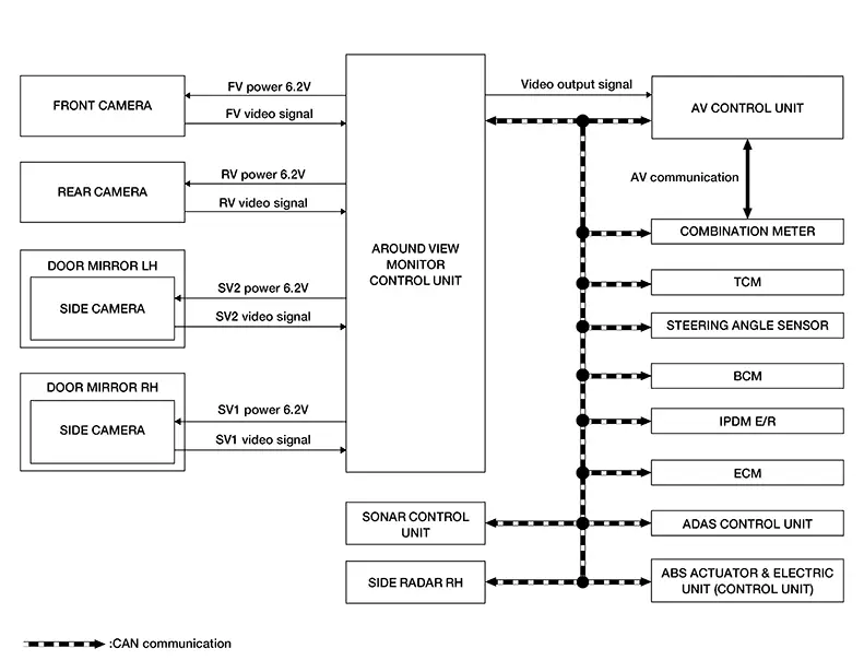
Around View Monitor Control Unit Input Signal (CAN Communication)
|
Transmit unit |
Signal name |
|---|---|
|
ABS actuator and electric unit (Control unit) |
Nissan Sentra Vehicle speed signal |
|
ADAS control unit |
Alert 1 and 2 signal |
|
AV control unit |
Camera switch signal |
|
BCM |
Door switch state signal |
|
Combination meter |
Parking brake signal |
|
ECM |
Pedal failure signal |
|
IPDM E/R |
Ignition supply signal |
|
Side radar RH |
right and left alert signal |
|
Sonar control unit |
Display request signal |
|
Steering Angle Sensor |
Steering wheel angle signal |
|
TCM |
Transmission range sensor signal |
DESCRIPTION
-
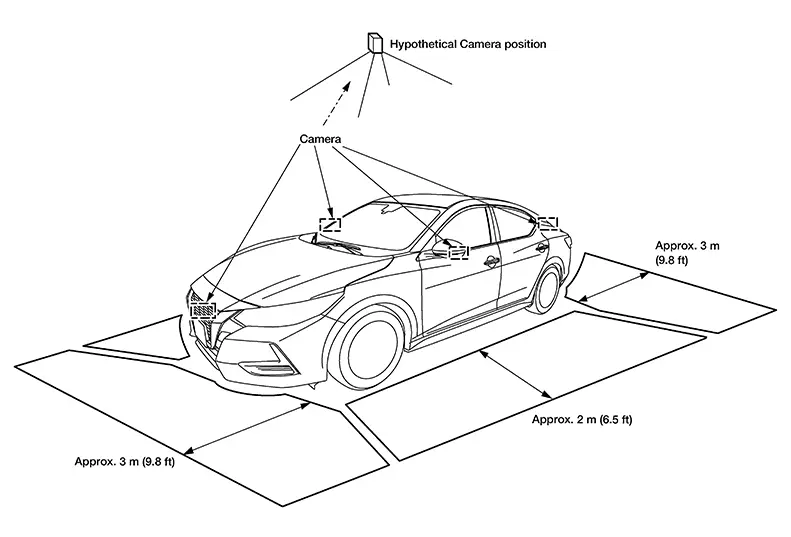
This system is equipped with wide-angle cameras on the front, rear and right and left door mirrors.
-
Images from front view, rear view, front-side view (RH side), and birds-eye view are displayed to monitor the Nissan Sentra vehicle surroundings.
-
Around view monitor control unit expands the image received from each camera to create each view.
-
In front view and rear view, the Nissan Sentra vehicle width, distance lines and predictive course lines are displayed.
-
In front-side view, the Nissan Sentra vehicle distance guiding line and vehicle width guiding line are displayed.
-
Birds-eye view converts the images from the cameras into an overhead view and displays the status of the Nissan Sentra vehicle on the AV control unit display. The vehicle icon that is displayed in the birds-eye view is depicted by the around view monitor control unit.
-
Moving Object Detection (MOD) is adopted and detects moving objects according to camera image and notifies the detection result to the driver.
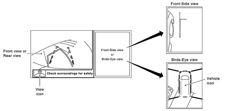
INTELLIGENT AROUND VIEW MONITOR DISPLAY
The Intelligent around view monitor combines and displays travel direction view (front or rear), front-side view and birds-eye view.
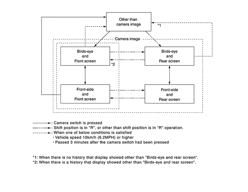
OPERATION DESCRIPTION
-
The Intelligent around view monitor operates by pressing the CAMERA switch on the AV control unit or by shifting to the R (reverse) position.
-
When the shift lever is in any position other than R (reverse) and the CAMERA switch is pressed, the screen displays front travel direction view and birds-eye view. Pressing the CAMERA switch again changes birds-eye view to front-side view
-
When the shift lever is placed in R (reverse), the screen displays rear travel direction view and birds-eye view. Pressing the CAMERA switch changes birds-eye view to front-side view
-
In birds-eye view, the blind spot area is displayed in black to show the border of the camera images. In addition, red fixed lines are displayed in the 4 corners of the Nissan Sentra vehicle icon. After pressing the CAMERA switch for the first time or placing the shift lever switch in R (reverse) for the first time, the blind spot area is highlighted in yellow for 3 seconds and the red fixed lines blink five times.
-
With the shift lever in any position other than R (reverse), the Intelligent around view monitor screen display is cancelled 3 minutes after pressing the CAMERA switch. The screen returns to the AV control unit display.
-
With the shift lever in R (reverse) position, the Intelligent around view monitor screen display remains on constantly. To return to the AV control unit display, place the shift lever in any position other than R (reverse).
-
If camera image calibration is incomplete, the applicable camera position is indicated as an error on the birds-eye view display.
Note:
Calibration is necessary when replacing each camera or when replacing around view monitor control unit.
Front View
-
The front view image improves the visibility of obstacles in front of the Nissan Sentra vehicle and assists driving by displaying images from birds-eye view and front-side view.
-
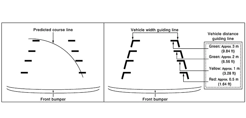
The front view image displays the Nissan Sentra vehicle width guiding line and vehicle distance guiding line, in addition to the predictive course line according to the steering angle.
-
If the steering angle is within approximately 90 degrees, the predictive course lines on the left/right side are displayed. If the steering angle exceeds approximately 90 degrees, only the predictive course line on the outside is displayed (opposite side of steering direction).
-
The around view monitor control unit receives the steering angle signal from steering angle sensor via CAN communication, and controls the direction and distance of the predictive course line.
-
ON/OFF setting of predictive course line can be performed using CONSULT.
Rear View
-
The rear view image improves the visibility of obstacles in the rear of the Nissan Sentra vehicle and assists backing and parking by displaying images from birds-eye view and rear view.
-
The rear view image displays the Nissan Sentra vehicle width guiding line and vehicle distance guiding line, in addition to the predictive course line according to the steering angle.
Note:
The predictive course line is not displayed at the steering neutral position.
-
The around view monitor control unit receives the steering angle signal from steering angle sensor via CAN communication, and controls the direction and distance of the predictive course line.
-
ON/OFF setting of predictive course line can be performed using CONSULT.
Rear view guiding lines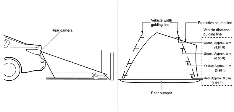
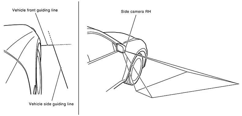
Front-side View
-
The front-side view image improves the visibility of obstacles in the front RH side of the Nissan Sentra vehicle and assists backing and parking.
-
The front-side view image displays the vehicle distance guiding line and Nissan Sentra vehicle width guiding line.
Birds-eye View
Birds-Eye View
-
The birds-eye view image improves the visibility of obstacles all around the Nissan Sentra vehicle and assists backing and parking.
-
The images from the four cameras are converted into an overhead view, and the surroundings of the Nissan Sentra vehicle are displayed.
-
The blind spot area is displayed on the image to specify the boundary of the four cameras.
 Birds-Eye view display area
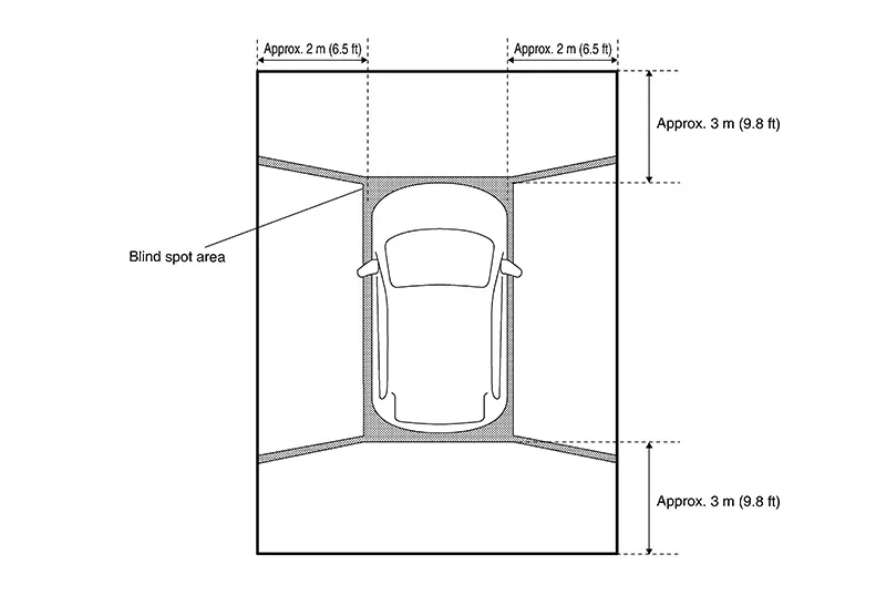
Moving Object Detection (MOD)
-
Moving Object Detection (MOD) is a function that notifies the driver of the presence of moving objects in the area around the Nissan Sentra vehicle. MOD detects moving objects from camera image, illuminates frame of view in yellow whenever “MOD” icon is displayed in blue.
-
Around view monitor control unit superimposes yellow frame line on camera image signal and outputs it to AV control unit display when moving objects are detected.
-
Around view monitor control unit detects moving objects from camera image according to an image recognition method called optical flow.
-
MOD does not detect a background as a moving object when the Nissan Sentra vehicle moves (when whole screen moves) but detects a moving object when an actual moving object is displayed on screen.
-
Color of “MOD” icon indicates whether or not MOD is operative. “MOD” icon is displayed as shown in the following table. when MOD is operative, “MOD” icon is displayed in blue. when MOD is not operative, “MOD” icon is displayed in gray.
View
Shift position
P, N or D position
R position
“MOD” icon display
Birds-Eye view and rear view
Birds-Eye view
—
Gray
Rear view
Blue
Birds-Eye view and front view
Birds-Eye view
Blue
—
Front view
Gray
Side view and rear view
Side view
—
Ă—
Rear view
Blue
Side view and front view
Side view
Ă—
—
Front view
Blue
Ă—: Icon is not displayed.
—: View is not displayed in each shift position (D position and R position).
-
MOD illuminates frame of view in yellow when any of the conditions in the following table are satisfied:
Operation Condition
View where MOD is operative
Shift position
Nissan Sentra Vehicle speed
P or N position
0 km/h
Birds-Eye view
D position
0 km/h (0 MPH) or more - less than 8 km/h (5 MPH)
Front view
R position
0 km/h (0 MPH) or more - less than 8 km/h (5 MPH)
Rear view
-
MOD does not operate or stops operation when any of the conditions in the following table are satisfied:
Operation stop condition
Note
Door open
-
MOD does not stop operation for front view.
-
Operation stops for rear view while trunk is open.
-
Operation stops for Bird’s-Eye view when any door is open.
-
CAMERA IMAGE OPERATION PRINCIPLE
-
If the information written to around view monitor control unit and the information from the camera do not match, the applicable camera position is indicated as an error on the Birds-Eye view display. (Calibration operation is necessary when replacing each camera or when replacing around view monitor control unit.)
-
Around view monitor control unit receives the camera switch signal from multifunction switch via CAN communication by pressing the “CAMERA” button.
-
Around view monitor control unit that receives the camera button signal supplies the power to each camera and inputs the camera image from each camera.
-
When the shift lever switch is in the reverse position, around view monitor control unit receives the reverse signal, supplies the power to each camera, and inputs the camera image from each camera.
-
Around view monitor control unit that receives the camera image signal from each camera cuts out the required screen for each view, superimposes the camera image, Nissan Sentra vehicle icon, guiding lines, sonar indicator and “MOD” icon and outputs them to the AV control unit.
CAMERA ASSISTANCE SONAR FUNCTION
-
Sonar sensors are installed on rear bumper. When an obstacle is detected while Intelligent around view monitor is displayed, a sonar indicator display and buzzer sound notify the driver of the proximity of an obstacle. When an obstacle is detected while Intelligent around view monitor is not displayed, Intelligent around view monitor screen is displayed automatically, and then notification is similar as while Intelligent around view monitor is displayed.
-
Approaching distance between bumper and obstacle is displayed in 3 stages according to the color of the sonar indicator in display and blinking cycle of indicator.
-
Warning by buzzer sound notifies distance to obstacle according to a 3-stage cycle.
Other materials:
U2140-87 Can Comm Err (ecm)
Dtc Description
DTC Description
DESCRIPTION
CAN (Controller Area Network) is a serial communication
line for real time applications. It is an on-Nissan Sentra vehicle multiplex communication
line with high data communication speed and excellent error detection
ability. Modern Nissan ...
Precaution. Precautions
Precautions
Precautions for Supplemental Restraint System (srs) Air Bag and Seat Belt Pre-Tensioner : Precautions
PRECAUTIONS FOR SUPPLEMENTAL RESTRAINT SYSTEM (SRS) AIR BAG AND SEAT BELT PRE-TENSIONER : Precautions
The Supplemental Restraint System such as
“AIR BAG” and “SEAT BELT P ...
Front Camera Unit
Values on the Diagnosis Tool
Values On The Diagnosis Tool
Note:
The following table includes information (items)
inapplicable to this Nissan Sentra vehicle. For information (items) applicable to this
vehicle, refer to CONSULT display items.
...