Nissan Sentra Service Manual: System
SRS air bag system
SRS AIR BAG SYSTEM : System Diagram
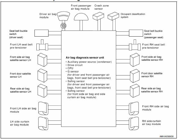
SRS AIR BAG SYSTEM : System Description
- The air bag deploys if the air bag diagnosis sensor unit is activated while the ignition switch is in the ON or START position.
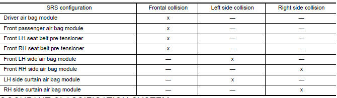
- The collision modes for which supplemental restraint systems are activated are different among the SRS systems. For example, the driver air bag module, front passenger air bag module and front seat belt pre-tensioners are activated in a frontal collision but not in a side collision.
SRS Collision Modes
Occupant classification system
OCCUPANT CLASSIFICATION SYSTEM : System Diagram
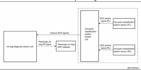
OCCUPANT CLASSIFICATION SYSTEM : System Description
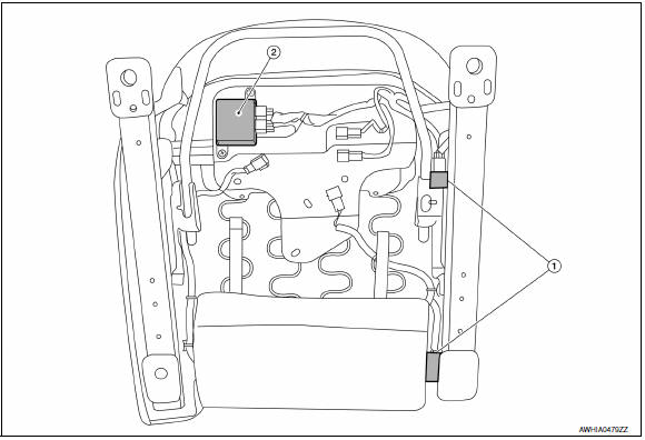
The occupant classification system (OCS) identifies different size occupants, out of position occupants, and detects if a child seat is present in the front passenger seat. The OCS control unit (2) receives inputs from the occupant classification sensors (1) (located inside the passenger seat cushion assembly). Depending on classification of the passenger, the OCS sends a signal to the air bag diagnosis sensor unit. The air bag diagnosis sensor unit uses this signal and the seat belt buckle switch (passenger seat) signal to determine deployment or non deployment of the passenger front air bag in the event of a collision. Depending on the signals received, the air bag diagnosis sensor unit can disable the passenger front air bag completely. The OCS (weight sensors) must be set to zero point using CONSULT after servicing the OCS system.
NOTE:
- CONSULT can be used to confirm when đ▓đéĐÜzero point resetđ▓đéĐť for OCS is complete
- Always perform zero point reset after the removal and installation of the seat or when disconnecting the OCS control unit harness connector even if zero point reset has been completed in the past.
- If zero point reset is incomplete, the passenger air bag will be disabled and the passenger air bag off indicator will be ON.
- In case of customer concern, CONSULT can be used to confirm the passenger air bag status (readiness).
Passenger Air Bag Status Conditions
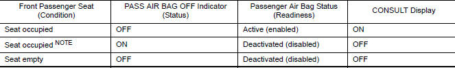
NOTE:
Passenger does not meet Occupant Classification System specifications for passenger air bag activation.
Seat belt warning lamp system
SEAT BELT WARNING LAMP SYSTEM : System Diagram
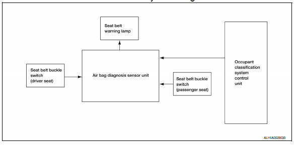
SEAT BELT WARNING LAMP SYSTEM : System Description
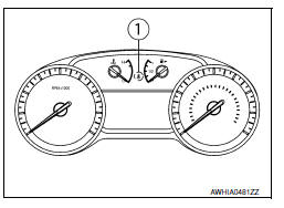
The seat belt warning lamp (1) will remind the driver if the driver or front passenger (US/CAN models) seat belt should be buckled. The system works in conjunction with the occupant classification system.
Refer to SRC-12, "OCCUPANT CLASSIFICATION SYSTEM : System Description".
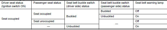
Seat Belt Warning System Operation
 Component parts
Component Parts Location
Driver air bag module
Front passenger air bag off indicator
Front passenger air bag module
Front LH side air bag module
(RH similar)
LH side curtain air bag ...
 Diagnosis system (AIR BAG)
Description
CAUTION:
Never use electrical test equipment on any circuit related to the
SRS unless instructed in this Service
Manual. SRS wiring harnesses can be identified by yellow and/or o ...
Other materials:
Basic inspection
Diagnosis and repair workflow
Work flow
Overall sequence
Detailed flow
1.Obtain information about symptom
Interview the customer to obtain as much information as possible about the
conditions and environment under
which the malfunction occurred.
>> GO TO 2.
2.Check symptom
...
Power supply and ground circuit
BCM (BODY CONTROL SYSTEM) (WITH INTELLIGENT KEY SYSTEM)
BCM (BODY CONTROL SYSTEM) (WITH INTELLIGENT KEY SYSTEM) : Diagnosis Procedure
Regarding Wiring Diagram information, refer to BCS-51, "Wiring Diagram".
1.Check fuses and fusible link
Check that the following fuses and fusible link ...
Bluetooth® Hands-Free Phone System voice commands
To access the Bluetooth® Hands-Free Phone
System voice commands:
Press the button.
Say ÔÇťCallÔÇŁ and then a name in the vehicle
phonebook to call that entry. Otherwise, say
ÔÇťPhoneÔÇŁ to access various phone commands.
If the Bluetooth┬« has been set to ÔÇťOffÔÇŁ, the
system announ ...
