Nissan Sentra B18 (2020-2025) Service Manual: Starting System :: System Description
Component Parts. Starting System (with Cvt)
Component Parts Location
Component Parts Location
|
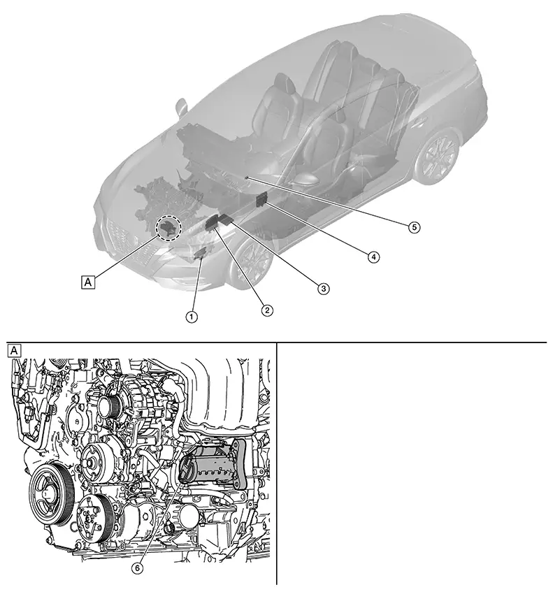
A. |
View with engine removed. |
|
No. |
Component |
Function |
|---|---|---|
|
1. |
TCM (Transmission Control Module) |
Refer to Component Parts Location for detailed component location. |
|
2. |
ECM (Engine Control Module) |
Refer to Component Parts Location for detailed component location. |
|
3. |
IPDM E/R (Intelligent Power Distribution Module Engine Room) |
CPU inside IPDM E/R operates the starter cut relay when the ignition switch is in the start position. Refer to System Description. |
|
4. |
BCM (Body Control Module) |
BCM controls the starter relay inside the IPDM E/R. Refer to System Description. |
|
5. |
Start/Stop off switch |
Supplies start/stop off switch status to the BCM. |
|
6. |
Starter motor |
Refer to Starter Motor. |
Starting System (with M/t)
Component Parts Location
Component Parts Location
|
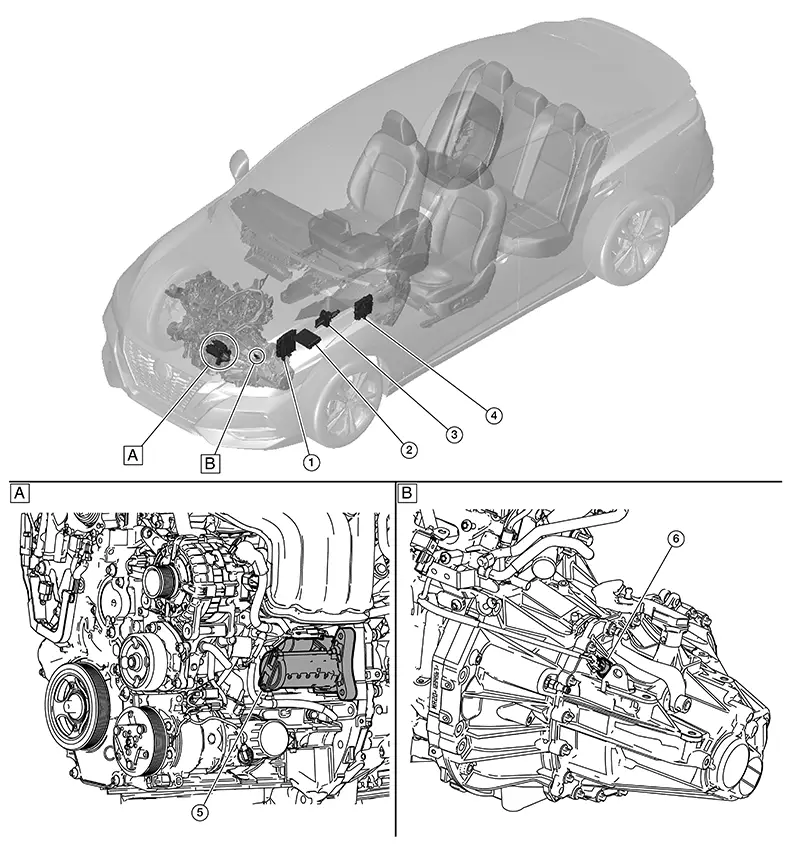
A. |
View with engine removed. |
B. |
View with transmission removed. |
|
No. |
Component |
Function |
|---|---|---|
|
1. |
ECM (Engine Control Module) |
CPU inside ECM communicates the signal from park/neutral position (PNP) switch. Refer to Component Parts Location for detailed component location. |
|
2. |
IPDM E/R (Intelligent Power Distribution Module Engine Room) |
CPU inside IPDM E/R operates the starter cut relay when the ignition switch is in the start position. Refer to System Description. |
|
3. |
Clutch master cylinder (clutch pedal position switch) |
Sends signal to BCM when clutch pedal is depressed. |
|
4. |
BCM (Body Control Module) |
BCM controls the starter relay inside IPDM E/R. Refer to System Description. |
|
5. |
Starter motor |
Refer to Starter Motor. |
|
6. |
Park/neutral position (PNP) switch |
Supplies the park/neutral position (PNP) switch signal to IPDM E/R and ECM. |
Starter Motor
Starter Motor
-
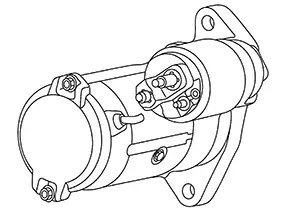
Starter motor is installed on LH side of engine.
-
The starter motor plunger closes and the motor is supplied with battery power, which in turn cranks the engine, when the “S” terminal is supplied with electric power.
-
“B” terminal: The “B” terminal is constantly supplied with battery power.
-
“S” terminal: The starter motor magnetic switch (“S” terminal) is supplied with power when the cranking condition is satisfied.
System. Starting System. Starting System
System Description
System Description
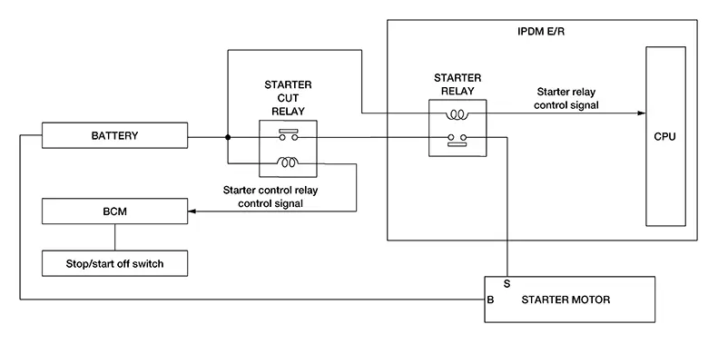
SYSTEM DIAGRAM
System Description
-
“B” terminal is constantly supplied with 12V battery power.
-
When starter operating condition is satisfied, IPDM E/R turns starter relay ON by starter relay control signal.
-
When engine cranking condition is satisfied, BCM turns starter cut relay ON by starter cut relay control signal.
-
Then 12V battery power is supplied to starter motor (“S” terminal) through starter cut relay and starter relay.
Other materials:
Heated Seat Does Not Operate. Diagnosis Procedure
Diagnosis Procedure
Diagnosis Procedure
CHECK HEATED SEAT RELAY
Check heated seat relay.
Refer to Component Function Check (LH) or Component Function Check (RH).
Is the inspection result normal?
YES>>
GO TO
...
B0012-55 Active Vent
Dtc Description
DTC Description
DTC DETECTION LOGIC
DTC No.
CONSULT screen items
(Trouble diagnosis
content)
DTC Detection Condition
...
P0315 Ckp Sensor (pos)
Dtc Description
DTC Description
DTC DETECTION LOGIC
DTC
CONSULT screen terms
(Trouble diagnosis
content)
DTC detection
condition
...