Nissan Sentra B18 (2020-2025) Service Manual: Sonar System :: Ecu Diagnosis Information. Sonar Control Unit
Sonar Control Unit. Values on the Diagnosis Tool
Values on the Diagnosis Tool
Note:
The following table includes information (items) inapplicable to this Nissan Sentra vehicle. For information (items) applicable to this vehicle, refer to CONSULT display items.
|
Monitor Item |
Condition |
Value/Status |
|---|---|---|
|
Nissan Sentra Vehicle SPEED |
While driving, equivalent to speedometer reading |
mph, km/h |
|
SONAR C/U POWER SUPPLY |
Key ON. |
Battery voltage |
|
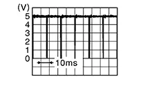
SENSOR VOLTAGE |
Key ON, selector lever in R (reverse) position. |
5.0 V |
|
DETECTION MODE |
Note:
Item is displayed, but cannot be monitored. |
|
|
SW OPRT AFTR IGN ON |
Note:
Item is displayed, but cannot be monitored. |
|
|
SONAR TEMPORARY OFF |
Note:
Item is displayed, but cannot be monitored. |
|
|
SONAR PERMANENT OFF |
Note:
Item is displayed, but cannot be monitored. |
|
|
P N RANGE |
When selector lever is in any position other than P (park) or N (neutral). |
Off |
|
When selector lever in P (park) or N (neutral) position. |
On |
|
|
LED |
Note:
Item is displayed, but cannot be monitored. |
|
|
REVERSE RANGE |
When transmission range switch is in any position other than R (reverse). |
Off |
|
When transmission range switch is in R (reverse) position. |
On |
|
|
SHRT DST FRM RR SENS |
Key ON, selector lever in R (reverse) position. |
cm/in |
|
COR[RL] |
||
|
COR[RL]→ CEN[RL]/CEN[R] |
||
|
CEN[RL]/CEN[R]→ COR[RL] |
||
|
CEN[RL]/CEN[R] |
||
|
CEN[RL]→ CEN[RR] |
||
|
CEN[RR]→ CEN[RL] |
||
|
CEN[RR] |
||
|
CEN[RR]/CEN[R]→ COR[RR] |
||
|
COR[RR]→ CEN[RR]/CEN[R] |
||
|
COR[RR] |
||
|
RVRB TIME COR[RL] |
Key ON, selector lever in R (reverse) position. |
ms/sec |
|
RVRB TIME COR[RR] |
||
|
RVRB TIME CEN[RL] |
||
|
RVRB TIME CEN[RR] |
||
|
FRONT BUZZER |
Key ON, buzzer ON. |
On |
|
Key ON, buzzer OFF. |
Off |
|
|
Buzzer request 1 (frequency) |
Note:
Item is displayed, but cannot be monitored. |
|
|
Buzzer request 2 (frequency) |
Note:
Item is displayed, but cannot be monitored. |
|
|
Buzzer request 3 (frequency) |
Note:
Item is displayed, but cannot be monitored. |
|
Reference Value
Reference Value
TERMINAL LAYOUT
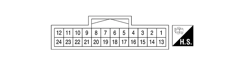
PHYSICAL VALUES
|
Terminal (Wire color) |
Description |
Condition |
Reference value (Approx.) |
|||
|---|---|---|---|---|---|---|
|
+ |
– |
Signal name |
Input/Output |
Ignition switch |
Operation |
|
|
5 (LA/L) |
— |
CAN-High |
Input/Output |
— |
— |
— |
|
6 (LA/R) |
— |
CAN-Low |
Input/Output |
— |
— |
— |
|
9 (BG) |
14 (SB) |
Rear sonar sensor RH inner |
Input |
ON |
Shift position is R (reverse). Obstacle within range of rear sonar sensor RH inner. |
 |
|
10 (V) |
14 (SB) |
Rear sonar sensor RH outer |
Input |
ON |
Shift position is R (reverse). Obstacle within range of rear sonar sensor RH outer. |
|
|
12 (LA/SB) |
Ground |
IGN power supply |
Input |
ON |
— |
Battery voltage |
|
14 (SB) |
Ground |
Rear sensor ground |
— |
ON |
— |
0 V |
|
15 (B) |
Ground |
Ground |
— |
ON |
— |
0 V |
|
18 (L) |
Ground |
Sonar buzzer signal |
Output |
ON |
Selector lever D (drive) or R (reverse) position and object within detection range |
Battery voltage |
|
19 (BR) |
Ground |
Sonar buzzer power supply |
Input |
ON |
Selector lever D (drive) or R (reverse) position |
Battery voltage |
|
21 (Y) |
14 (SB) |
Rear sonar sensor LH inner |
Input |
ON |
Shift position is R (reverse). Obstacle within range of rear sonar sensor LH inner. |
|
|
22 (R) |
14 (SB) |
Rear sonar sensor LH outer |
Input |
ON |
Shift position is R (reverse). Obstacle within range of rear sonar sensor LH outer. |
|
|
23 (GR) |
Ground |
Rear sonar sensor power |
Output |
ON |
— |
Battery voltage |
Fail-Safe
Fail-Safe
|
Display contents of CONSULT |
Fault |
Fail-safe operation |
|---|---|---|
|
B2720–60: CORNER SENSOR [RL] B2720–61: CORNER SENSOR [RL] B2720–62: CORNER SENSOR [RL] B2720–63: CORNER SENSOR [RL] B2720–65: CORNER SENSOR [RL] B2720–67: CORNER SENSOR [RL] B2720–68: CORNER SENSOR [RL] B2720–83: CORNER SENSOR [RL] B2720–92: CORNER SENSOR [RL] B2721–60: CENTER SENSOR [RL] B2721–61: CENTER SENSOR [RL] B2721–62: CENTER SENSOR [RL] B2721–63: CENTER SENSOR [RL] B2721–65: CENTER SENSOR [RL] B2721–67: CENTER SENSOR [RL] B2721–68: CENTER SENSOR [RL] B2721–83: CENTER SENSOR [RL] B2721–92: CENTER SENSOR [RL] B2722–60: CENTER SENSOR [RR] B2722–61: CENTER SENSOR [RR] B2722–62: CENTER SENSOR [RR] B2722–63: CENTER SENSOR [RR] B2722–65: CENTER SENSOR [RR] B2722–67: CENTER SENSOR [RR] B2722–68: CENTER SENSOR [RR] B2722–83: CENTER SENSOR [RR] B2722–92: CENTER SENSOR [RR] B2723–60: CORNER SENSOR [RR] B2723–61: CORNER SENSOR [RR] B2723–62: CORNER SENSOR [RR] B2723–63: CORNER SENSOR [RR] B2723–65: CORNER SENSOR [RR] B2723–67: CORNER SENSOR [RR] B2723–68: CORNER SENSOR [RR] B2723–83: CORNER SENSOR [RR] B2723–92: CORNER SENSOR [RR] |
Sensor internal failure |
Obstacle detection of the sensor in error is stopped |
|
B2720–66: CORNER SENSOR [RL] B2721–66: CENTER SENSOR [RL] B2722–66: CENTER SENSOR [RR] B2723–66: CORNER SENSOR [RR] |
Open circuit/short circuit to ground |
|
|
B2724–23: SONAR CONTROL UNIT B2724–24: SONAR CONTROL UNIT |
Sonar control unit internal failure (under voltage) |
|
|
B2724–44: SONAR CONTROL UNIT B2724–45: SONAR CONTROL UNIT B2724–46: SONAR CONTROL UNIT B2724–48: SONAR CONTROL UNIT B2724–49: SONAR CONTROL UNIT B2724–86: SONAR CONTROL UNIT B2724–87: SONAR CONTROL UNIT |
Sonar control unit internal failure |
|
|
B2724–55: SONAR CONTROL UNIT |
Sonar control unit internal failure (not configured) |
|
|
B272D–12: FRONT BUZZER |
|
Audible warning (sonar buzzer) of all sensors is stopped. |
|
B272D–14: FRONT BUZZER |
|
|
|
B273B-11: REAR SENSOR POWER |
Rear sensor power supply is short to ground |
Obstacle detection function is deactivated |
|
B273B-12: REAR SENSOR POWER |
Rear sensor power supply is short to voltage |
|
|
B273B-87: REAR SENSOR POWER |
Connection error is detected between sonar control unit and rear sonar sensors |
|
|
U0073–00: Control module comm Bus A Off U0075–00: Control module comm Bus C Off U1000–00: CAN COMM CIRCUIT U1010–00: CONTROL UNIT(CAN) |
CAN communication system |
Obstacle detection is disabled |
|
U2141–87: CAN comm err (TCM) |
CAN communication system (TCM) |
|
|
U2148–87: CAN comm err (brake control unit) |
CAN communication system [ABS actuator and electric unit (control unit)] |
|
|
U214E–87: CAN comm err (combination meter) |
CAN communication system (combination meter) |
|
|
U214F–87: CAN comm err (BCM) |
CAN communication system (BCM) |
|
|
U2152–87: CAN comm err (ADAS control unit) |
CAN communication system (ADAS control unit) |
|
|
U215B–87: CAN comm err (IPDM E/R) |
CAN communication system (IPDM E/R) |
Dtc Inspection Priority Chart
DTC Inspection Priority Chart
If multiple DTCs are detected simultaneously, check them one by one depending on the following DTC inspection priority chart:
|
Priority |
Detected items (DTC) |
|---|---|
|
1 |
|
|
2 |
|
Dtc Index
DTC Index
|
CONSULT Display |
Reference Page |
|---|---|
|
B2720–60: CORNER SENSOR [RL] |
DTC Description |
|
B2720–61: CORNER SENSOR [RL] |
|
|
B2720–62: CORNER SENSOR [RL] |
|
|
B2720–63: CORNER SENSOR [RL] |
|
|
B2720–65: CORNER SENSOR [RL] |
|
|
B2720–66: CORNER SENSOR [RL] |
|
|
B2720–67: CORNER SENSOR [RL] |
|
|
B2720–68: CORNER SENSOR [RL] |
|
|
B2720–83: CORNER SENSOR [RL] |
|
|
B2720–92: CORNER SENSOR [RL] |
|
|
B2721–60: CENTER SENSOR [RL] |
DTC Description |
|
B2721–61: CENTER SENSOR [RL] |
|
|
B2721–62: CENTER SENSOR [RL] |
|
|
B2721–63: CENTER SENSOR [RL] |
|
|
B2721–65: CENTER SENSOR [RL] |
|
|
B2721–66: CENTER SENSOR [RL] |
|
|
B2721–67: CENTER SENSOR [RL] |
|
|
B2721–68: CENTER SENSOR [RL] |
|
|
B2721–83: CENTER SENSOR [RL] |
|
|
B2721–92: CENTER SENSOR [RL] |
|
|
B2722–60: CENTER SENSOR [RR] |
DTC Description |
|
B2722–61: CENTER SENSOR [RR] |
|
|
B2722–62: CENTER SENSOR [RR] |
|
|
B2722–63: CENTER SENSOR [RR] |
|
|
B2722–65: CENTER SENSOR [RR] |
|
|
B2722–66: CENTER SENSOR [RR] |
|
|
B2722–67: CENTER SENSOR [RR] |
|
|
B2722–68: CENTER SENSOR [RR] |
|
|
B2722–83: CENTER SENSOR [RR] |
|
|
B2722–92: CENTER SENSOR [RR] |
|
|
B2723–60: CORNER SENSOR [RR] |
DTC Description |
|
B2723–61: CORNER SENSOR [RR] |
|
|
B2723–62: CORNER SENSOR [RR] |
|
|
B2723–63: CORNER SENSOR [RR] |
|
|
B2723–65: CORNER SENSOR [RR] |
|
|
B2723–66: CORNER SENSOR [RR] |
|
|
B2723–67: CORNER SENSOR [RR] |
|
|
B2723–68: CORNER SENSOR [RR] |
|
|
B2723–83: CORNER SENSOR [RR] |
|
|
B2723–92: CORNER SENSOR [RR] |
|
|
B2724–23: SONAR CONTROL UNIT |
DTC Description |
|
B2724–24: SONAR CONTROL UNIT |
|
|
B2724–44: SONAR CONTROL UNIT |
|
|
B2724–45: SONAR CONTROL UNIT |
|
|
B2724–46: SONAR CONTROL UNIT |
|
|
B2724–48: SONAR CONTROL UNIT |
|
|
B2724–49: SONAR CONTROL UNIT |
|
|
B2724–55: SONAR CONTROL UNIT |
|
|
B2724–86: SONAR CONTROL UNIT |
|
|
B2724–87: SONAR CONTROL UNIT |
|
|
B272D-12: FRONT BUZZER |
DTC Description |
|
B272D-14: FRONT BUZZER |
|
|
B273B-11: REAR SENSOR POWER |
DTC Description |
|
B273B-12: REAR SENSOR POWER |
|
|
B273B-87: REAR SENSOR POWER |
|
|
U0073–00: Control module comm Bus A Off |
DTC Description |
|
U0075–00: Control module comm Bus C Off |
DTC Description |
|
U1000-00: CAN COMM CIRCUIT |
DTC Description |
|
U1010-00: CONTROL UNIT(CAN) |
DTC Description |
|
U2141–87: CAN comm err (TCM) |
DTC Description |
|
U2148–87: CAN comm err (brake control unit) |
DTC Description |
|
U214E–87: CAN comm err (combination meter) |
DTC Description |
|
U214F–87: CAN comm err (BCM) |
DTC Description |
|
U2152–87: CAN comm err (ADAS control unit) |
DTC Description |
|
U215B–87: CAN comm err (IPDM E/R) |
DTC Description |
Other materials:
Intelligent Key Battery. Removal and Installation
Removal and Installation
Removal and
Installation
Release the lock knob at the back of the Intelligent
Key and remove the mechanical key.
Insert remover tool (A) wrapped with a cloth into
the slit of the corner and twist it to separate the upper par ...
P0746-00 Pressure Control Solenoid a
Dtc Description
DTC Description
DTC DETECTION LOGIC
DTC
CONSULT screen terms
(Trouble diagnosis
content)
DTC detection
conditi ...
C1601-16 Battery Power Supply
Dtc Description
DTC Description
DTC DETECTION LOGIC
DTC No.
CONSULT screen terms
(Trouble diagnosis content)
DTC detection condition
...