Nissan Sentra B18 (2020-2025) Service Manual: Removal and Installation
Front Camera Unit
Exploded View
Exploded View
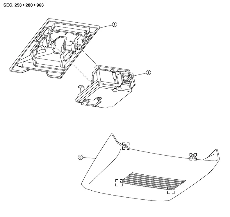
|
1. |
Front camera unit bracket |
2. |
Front camera unit |
3. |
Front camera cover |
|
|
Metal clip |
|
Pawl |


Removal and Installation
Removal and Installation
REMOVAL
CAUTION:
-
Do not remove front camera unit bracket and front camera cover from windshield glass.
-
Front camera unit bracket and front camera cover must be replaced together with windshield glass as an assembly.
-
When replacing front camera unit, perform “ADDITIONAL SERVICE WHEN REPLACING FRONT CAMERA UNIT." Refer to Work Procedure.
Remove front camera cover.
Disconnect harness connector from front camera unit.
Using a
suitable tool, release pawls (A) and remove front camera
unit. 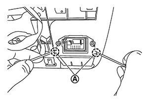
INSTALLATION
Installation is in the reverse order of removal.
CAUTION:
-
Be sure to perform "ADDITIONAL SERVICE WHEN REPLACING FRONT CAMERA UNIT" when replacing front camera unit. Refer to Work Procedure.
-
Do not touch or shock front camera lens area or drop front camera unit.
-
Perform camera aiming every time the front camera unit is removed and installed. Refer to Work Procedure.
Distance Sensor
Exploded View
Exploded View
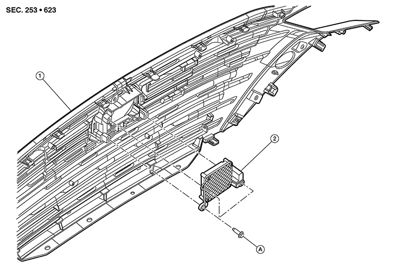
|
1. |
Front grille |
2. |
Distance sensor |
A. |
Refer to Removal and Installation. |
Removal and Installation
Removal and Installation
REMOVAL
Remove clips (A) and core support
cover (1). 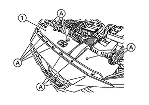
Remove bolt from front bumper fascia side retainer (LH). Refer to Exploded View.
Remove air inlet duct clips and remove air inlet duct. Refer to Exploded View.
Remove bolts from hood lock and position the hood lock aside. Refer to Exploded View.
Remove clips and position the air guide (upper) aside. Refer to Exploded View.
Disconnect the harness connector from distance sensor.
Remove bolts and remove distance sensor.
INSTALLATION
Installation is in the reverse order of removal.
Install distance sensor to the front
grille and tighten bolts to specification in sequence shown. 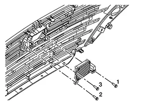
|
Distance sensor bolts |
: 4.9 N·m (0.50 kg-m, 43 in-lb) |
CAUTION:
-
If distance sensor is being replaced or has been disconnected, perform "ADDITIONAL SERVICE WHEN REPLACING DISTANCE SENSOR". Refer to Work Procedure.
-
Do not touch distance sensor face.
-
Do not drop or shock distance sensor.
-
Make sure distance sensor harness is installed without any twists.
Driver Assistance Buzzer
Removal and Installation
Removal and Installation
REMOVAL
Remove left knee air bag module. Refer to Removal and Installation.
Remove steering column covers. Refer to Removal and Installation.
Remove screw (A) from driver assistance
buzzer (1). 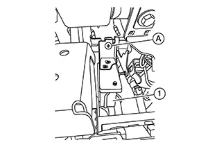
Disconnect harness connector and remove driver assistance buzzer.
INSTALLATION
Installation is in the reverse order of removal.
Side Radar
Exploded View
Exploded View
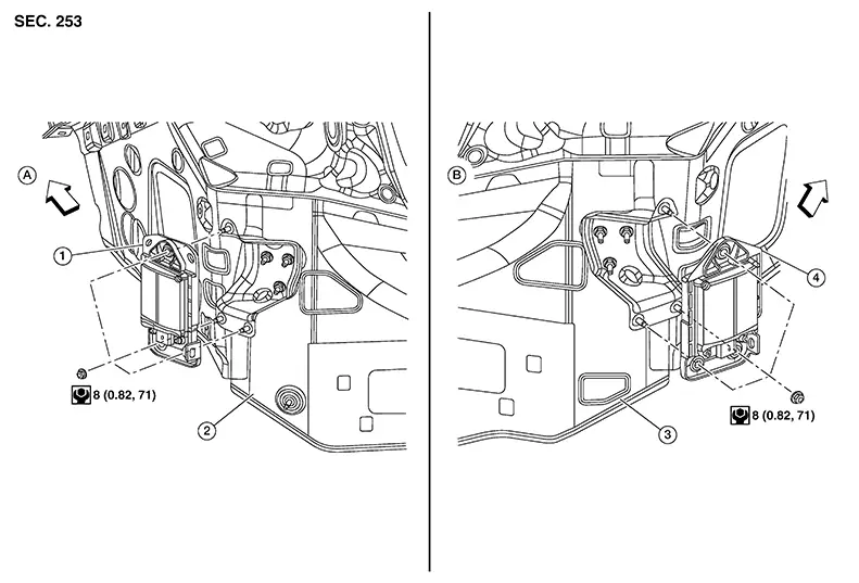
|
1. |
Side radar (LH) |
2. |
Rear fender (LH) |
3. |
Rear fender (RH) |
|
4. |
Side radar (RH) |
A. |
LH side |
B. |
RH side |
|
|
Front |

Removal and Installation
Removal and Installation
REMOVAL
Remove rear bumper fascia. Refer to Removal and Installation.
Disconnect harness connector from side radar.
Remove nuts from side radar and remove side radar.
INSTALLATION
Installation is in the reverse order of removal.
CAUTION:
-
Do not use side radar if lens has flaws.
-
Perform Blind Spot Warning system action test after side radar installation is complete. Refer to Work Procedure.
-
Perform the Rear Cross Traffic Alert action test after side radar installation is complete. Refer to Work Procedure.

Do not touch side radar lens and keep lens area clean.
Bsw Indicator
Removal and Installation
Removal and Installation
REMOVAL
Note:
LH shown; RH similar
Remove front door finisher. Refer to Removal and Installation.
Using a
suitable tool, release clips from door mirror corner finisher (3)
in the sequence shown.
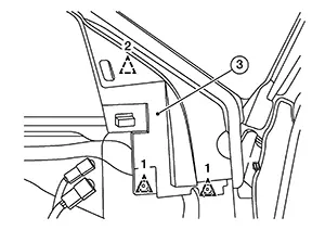
|
|
: Clip |

Disconnect
harness connector (A) from BSW indicator (1).
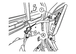
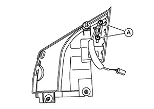
Remove
screws (A) and remove BSW indicator.
INSTALLATION
Installation is in the reverse order of removal.
Other materials:
Diagnosis System (distance Sensor)
Consult Function (laser/radar)
CONSULT Function (LASER/RADAR)
APPLICATION ITEMS
CONSULT performs the following functions via CAN communication
with ADAS control unit 2 and the communication with distance sensor.
...
Horn. Precaution. Precautions. Precaution for Supplemental Restraint System (srs) "air Bag" and "seat Belt Pre-Tensioner"
Precautions. Precaution for Supplemental Restraint System (srs) "air Bag" and "seat Belt Pre-Tensioner"
Precaution for Supplemental Restraint System (srs) "air Bag" and "seat Belt Pre-Tensioner"
Precaution for Supplemental Restraint System (SRS) "AIR BAG" an ...
C161a-83 Abs System
Dtc Description
DTC Description
DTC DETECTION LOGIC
DTC No.
CONSULT screen terms
(Trouble diagnosis content)
DTC detection condition
...