Nissan Sentra B18 (2020-2025) Service Manual: Removal and Installation
Av Control Unit
Exploded View
Exploded View
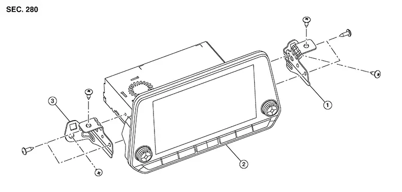
|
1. |
AV control unit bracket (LH) |
2. |
AV control unit |
3. |
AV control unit bracket (RH) |
Removal and Installation
Removal and Installation
REMOVAL
CAUTION:
When replacing AV control unit, perform "ADDITIONAL SERVICE WHEN REPLACING AV CONTROL UNIT. Refer to Work Procedure.
Disconnect the negative battery terminal. Refer to Battery Disconnect.
Remove cluster lid C. Refer to Removal and Installation
Remove the AV control unit screws, then pull out the AV control unit.
Disconnect the harness connectors from the AV control unit and remove.
If necessary, remove the AV control unit bracket (LH/RH) screws and the AV control unit brackets (LH/RH).
INSTALLATION
Installation is in the reverse order of removal.
CAUTION:
When replacing AV control unit, perform "ADDITIONAL SERVICE WHEN REPLACING AV CONTROL UNIT". Refer to Work Procedure.
Steering Switches
Exploded View
Exploded View
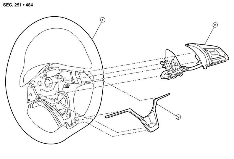
|
1. |
Steering wheel |
2. |
Steering wheel finisher |
3. |
Steering switches |
Removal and Installation
Removal and Installation
REMOVAL
Note:
The steering switches are serviced as an assembly.
Remove driver air bag. Refer to Removal and Installation.
Release
pawls on the steering wheel front finisher (1) using suitable tool
and remove from the steering wheel.
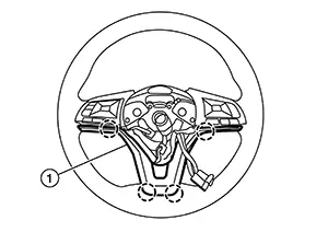
|
|
: Pawl |

Release
pawls on the steering switches (1) using suitable tool and remove
from the steering wheel.
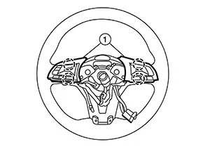
|
|
: Pawl |
Disconnect steering switch connector from spiral cable and remove from Nissan Sentra vehicle.
INSTALLATION
Installation is in the reverse order of removal.
Microphone
Removal and Installation
Removal and Installation
REMOVAL
Remove the front room/map lamp assembly. Refer to Removal and Installation.
Release
pawls and remove microphone (1) from the front room/map lamp
assembly. 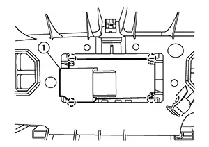
|
|
: Pawl |
INSTALLATION
Installation is in the reverse order of removal.
Front Auxiliary Input Jacks
Removal and Installation
Removal and Installation
REMOVAL
Remove cluster lid C. Refer to Removal and Installation.
Using a
suitable tool, release pawls on the front auxiliary input jacks
(1), then remove from the front of cluster lid C (2). 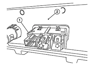
|
|
: Pawl |
INSTALLATION
Installation is in the reverse order of removal.
Front Auxiliary Input Jacks Control Unit
Removal and Installation
Removal and Installation
Removal
Remove instrument finisher B. Refer to Removal and Installation.
Remove
screw (A) from steering member (1). 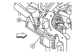
|
|
: Front |

Disconnect
the harness connectors from the front auxiliary input jacks control
unit (1) and remove. 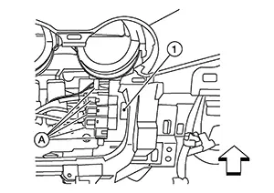
|
|
: Front |
Installation
Installation is in the reverse order of removal.
Front Tweeter
Exploded View
Exploded View
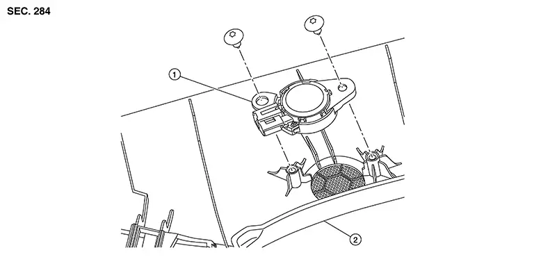
|
1. |
Front tweeter |
2. |
Front pillar finisher |
Removal and Installation
Removal and Installation
REMOVAL
Remove front pillar finisher. Refer to Removal and Installation.
Remove screws from front tweeter and remove.
INSTALLATION
Installation is in the reverse order of removal.
Front Door Speaker
Exploded View
Exploded View
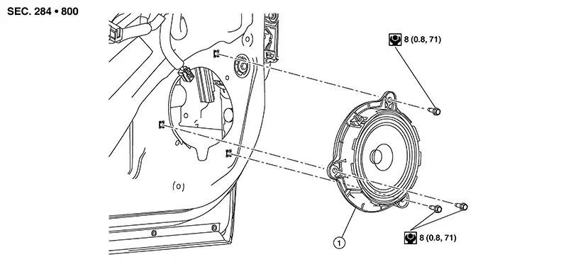
|
1. |
Front door speaker |
Removal and Installation
Removal and Installation
REMOVAL
Remove front door finisher. Refer to Removal and Installation.
Remove front door speaker bolts, then pull out front door speaker.
Disconnect the harness connector from front door speaker and remove.
INSTALLATION
Installation is in the reverse order of removal.
Rear Door Speaker
Exploded View
Exploded View
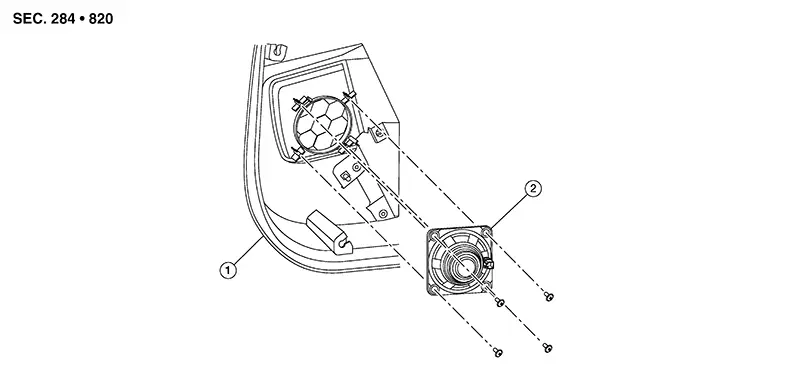
|
1. |
Rear door finisher |
2. |
Rear door speaker |
Removal and Installation
Removal and Installation
REMOVAL
Remove rear door finisher. Refer to Removal and Installation.
Remove bolts and remove rear door speaker.
INSTALLATION
Installation is in the reverse order of removal.
Bose® Speaker Amp
Removal and Installation
Removal and Installation
REMOVAL
Remove
bolts (A) from Bose® speaker amp (1). 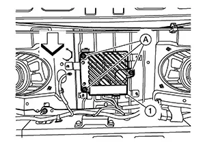
Disconnect the harness connectors from Bose® speaker amp and remove.
If necessary, remove the rear parcel shelf finisher to expose the Bose® speaker amp bracket bolts. Refer to Removal and Installation.
If
necessary, remove bolts (A) from the Bose® speaker amp bracket
(1) and remove the Bose® speaker amp bracket. 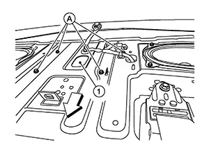
|
|
: Front |
INSTALLATION
Installation is in the reverse order of removal.
Antenna Amp
Removal and Installation
Removal and Installation
Removal
Remove passenger side rear pillar finisher. Refer to Removal and Installation — Rear Pillar Upper Finisher.
Remove
screw (A) from antenna amp (1). 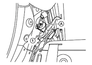
Disconnect the harness connector and remove the antenna amp.
Installation
Installation is in the reverse order of removal.
Satellite Antenna
Exploded View
Exploded View
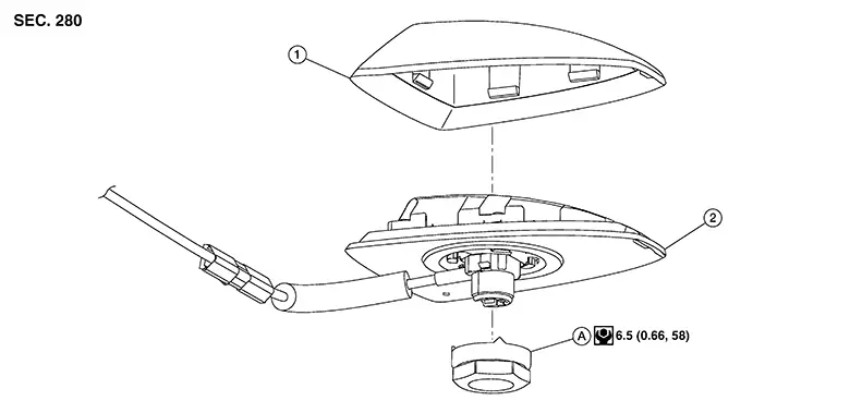
|
1. |
Outer cover |
2. |
Satellite antenna |
A. |
Satellite antenna nut |
Removal and Installation
Removal and Installation
REMOVAL
Remove headlining. Refer to Removal and Installation.
Disconnect harness connectors from satellite antenna.
Remove satellite antenna nut from satellite antenna and remove.
INSTALLATION
Installation is in the reverse order of removal.
CAUTION:
If the satellite antenna nut is not properly tightened, lower sensitivity of the antenna may be experienced. If the nut is over tightened, this will deform the roof panel.
Disassembly and Assembly
Disassembly and Assembly
Disassembly
Remove satellite antenna. Refer to Removal and Installation.
Using a
suitable tool, release pawls and remove outer cover (1) from
satellite antenna (2). 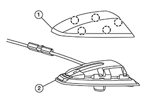
Assembly
Assembly is in the reverse order of disassembly.
Other materials:
Horn. Precaution. Precautions. Precaution for Supplemental Restraint System (srs) "air Bag" and "seat Belt Pre-Tensioner"
Precautions. Precaution for Supplemental Restraint System (srs) "air Bag" and "seat Belt Pre-Tensioner"
Precaution for Supplemental Restraint System (srs) "air Bag" and "seat Belt Pre-Tensioner"
Precaution for Supplemental Restraint System (SRS) "AIR BAG" an ...
Cannot Set Automatic Speed Control Device (ascd)
Diagnosis Procedure
Diagnosis Procedure
PERFORM SELF-DIAGNOSIS
With CONSULT
Perform ECM self-diagnosis.
Is DTC detected?
YES >>
Perform diagnosis of applicable.
NO >>
GO TO 2.
CHECK BRAKE PEDAL POSITION SWITCH
...
B2f06-15 Back Door/trunk Opener Switch
Dtc Description
DTC Description
DTC DETECTION LOGIC
DTC No.
CONSULT screen items (Trouble
diagnosis content)
DTC detecting condition
...