Nissan Sentra Service Manual: Removal and installation
OIL COOLER
Exploded View
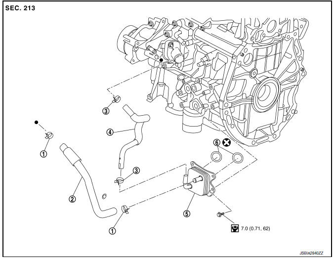
M/T models
- Clamp
- Water hose
- Clamp
- Water hose
- Oil cooler
- O-rings
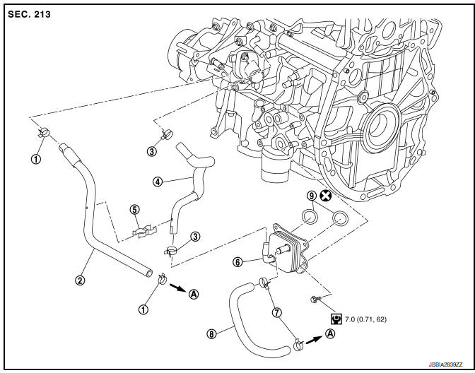
CVT models
- Clamp
- Water hose
- Clamp
- Water hose
- Water hose clip
- Oil cooler
- Clamp
- Water hose
- O-rings
- To CVT oil warmer
Removal and Installation
REMOVAL
- Remove engine under cover. Refer to EXT-16, "Exploded View".
- Drain engine coolant. Refer to CO-12, "Changing Engine Coolant".
CAUTION:
Perform when engine is cold.
- Remove water hoses.
- Remove bolts, oil cooler and O-rings.
CAUTION:
- Be careful not to get burned when engine and engine oil may be hot.
- When removing, prepare a shop cloth to absorb any engine oil leaks or spills.
- Completely wipe off any engine oil that adheres to engine and vehicle.
INSTALLATION
Installation is in the reverse order of removal.
CAUTION:
Do not reuse O-rings.
NOTE:
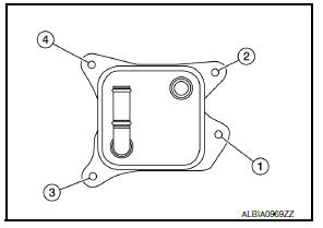
Tighten the oil cooler bolts in order as shown to specification.
Inspection
INSPECTION AFTER REMOVAL
Oil Cooler
Check oil cooler for cracks. Check oil cooler for clogging by blowing through engine coolant inlet. If necessary, replace oil cooler assembly.
INSPECTION AFTER INSTALLATION
- Check the engine oil level and the engine coolant level and add engine oil and engine coolant. Refer to LU-7, "Inspection" and CO-11, "System Inspection".
- Start the engine, and check that there are no leaks of engine oil or engine coolant.
- Stop the engine and wait for 10 minutes.
- Check the engine oil level and the engine coolant level again. Refer to LU-7, "Inspection" and CO-11, "System Inspection".
 Oil filter
Removal and Installation
REMOVAL
Remove engine under cover. Refer to EXT-16, "Exploded View".
Drain engine oil. Refer to LU-8, "Draining".
Remove the oil filter using Too ...
 Unit disassembly and assembly
OIL PUMP
O-ring
Oil pan (upper)
Oil level gauge guide
O-ring
Oil level gauge
Oil pump chain tensioner
Oil pump drive chain
Crankshaft sprocket
Oil pump sprocket
Oil pump
Dr ...
Other materials:
Rear window defogger relay
Description
Power is supplied to the rear window defogger with BCM control.
Component Function Check
1. Check rear window defogger relay power supply circuit
Turn ignition switch ON.
Check that an operation noise of rear window defogger relay (located in
IPDM E/R) can be heard when
t ...
Controls
Fan control dial
The fan control dial turns the fan on and off, and
controls fan speed.
Air flow control buttons
The air flow control buttons allow you to select
the air flow outlets.
MAX — Air flows from center and side
A/Cvents with maximum cooling.
— Air flows from center and side
v ...
Windshield-washer fluid
Windshield-washer fluid reservoir
Fill the windshield-washer fluid reservoir periodically.
To fill the windshield-washer fluid reservoir, lift
the cap off the reservoir and pour the windshieldwasher
fluid into the reservoir opening.
Add a washer solvent to the washer for better
cleanin ...
