Nissan Sentra Service Manual: Unit disassembly and assembly
OIL PUMP
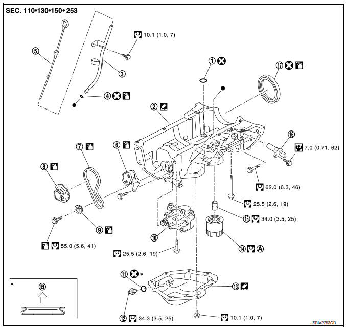
- O-ring
- Oil pan (upper)
- Oil level gauge guide
- O-ring
- Oil level gauge
- Oil pump chain tensioner
- Oil pump drive chain
- Crankshaft sprocket
- Oil pump sprocket
- Oil pump
- Drain plug washer
- Drain plug
- Oil pan (lower)
- Oil filter
- Connector bolt
- Crankshaft position sensor
- Rear oil seal
- Refer to LU-10, "Removal and Installation"
- Oil pan side
Removal and Installation
REMOVAL
- Remove engine under cover. Refer to EXT-16, "Exploded View".
- Remove air cleaner and air duct. Refer toEM-25, "Removal and Installation".
- Remove fender protector. Refer to EXT-28, "FENDER PROTECTOR : Removal and Installation - Front Fender Protector".
- Remove timing chain. Refer to EM-49, "Removal and Installation".
- Remove oil pump.
- Loosen bolts in reverse order as shown.
(1) : Oil pump
(2) : Oil pan (upper)
INSTALLATION
CAUTION:
Do not reuse O-rings or washers.
Installation is in the reverse order of removal.
Oil Pump
- Tighten bolts in numerical order as shown.
(1) : Oil pump
(2) : Oil pan (upper)
Inspection
INSPECTION AFTER INSTALLATION
- Check the engine oil level. Refer to LU-7, "Inspection".
- Start the engine, and check that there are no leaks of engine oil.
- Stop the engine and wait for 10 minutes.
- Check the engine oil level, and adjust the level. Refer to LU-7, "Inspection".
 Removal and installation
OIL COOLER
Exploded View
M/T models
Clamp
Water hose
Clamp
Water hose
Oil cooler
O-rings
CVT models
Clamp
Water hose
Clamp
Water hose
Water hose clip
Oil coole ...
 Service data and specifications
(SDS)
Service data and specifications
(SDS)
Oil pressure
*: Engine oil temperature at 80В°C (176В°F)
Oil Capacity
...
Other materials:
Water pump
Exploded View
Gasket
Water pump
WARNING:
Do not remove the radiator cap when the engine is hot. Serious burns
could occur from high-pressure
engine coolant escaping from the radiator. Wrap a thick cloth around the cap.
Slowly push down and
turn it a quarter turn to allow built-up ...
Wiring diagram
Sport mode system
Wiring diagram
...
P0420 Three way catalyst function
DTC Logic
DTC DETECTION LOGIC
The ECM monitors the switching frequency ratio of air fuel ratio (A/F)
sensor 1 and heated oxygen sensor 2.
A three way catalyst (manifold) with high oxygen storage capacity
will indicate a low switching frequency of heated oxygen sensor 2.
As oxygen storage c ...
