Nissan Sentra B18 (2020-2025) Service Manual: Removal and Installation
Front Wheel Sensor
Exploded View
Exploded View
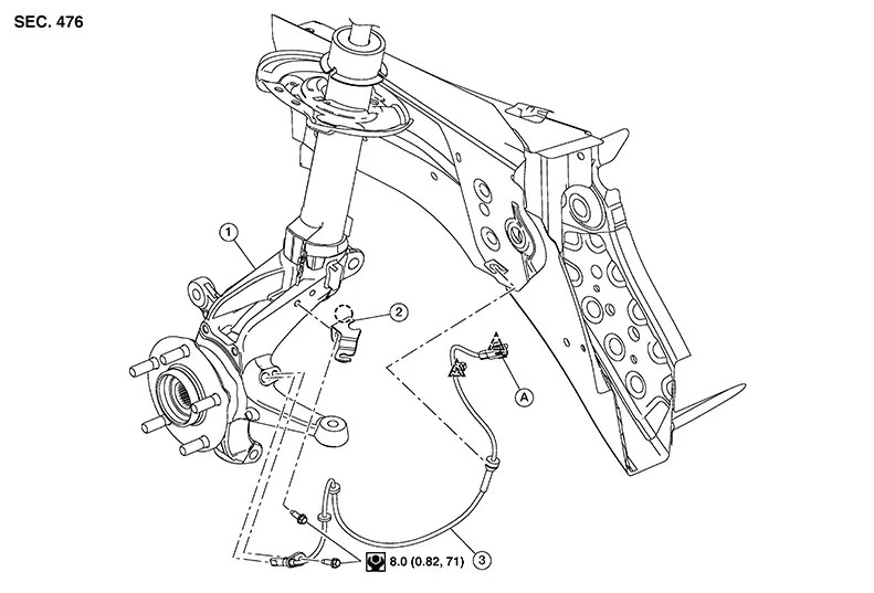
|
1. |
Steering knuckle |
2. |
Sensor bracket |
3. |
Front wheel sensor |
|
A. |
Harness connector |
|
Pawl |
|
Clip |


Removal and Installation
Removal and Installation
CAUTION:
-
Be careful not to damage the front wheel sensor edge and the sensor rotor teeth.
-
When removing the wheel bearing, first remove the front wheel sensor from the steering knuckle. Failure to do so may result in damage to the front wheel sensor wires making the front wheel sensor inoperative.
REMOVAL
Remove the front wheel and tire using power tool. Refer to Removal and Installation.
Partially remove the fender protector to gain access to the harness connector. Refer to Exploded View.
Release the clips using a suitable tool. Refer to Exploded View.
Disconnect the harness connector from the front wheel sensor.
Remove the front wheel sensor from the sensor brackets.
Remove the front wheel sensor bolt from the steering knuckle.
Remove the front wheel sensor.
CAUTION:
Pull out the front wheel sensor, being careful to turn it as little as possible. Do not pull on the front wheel sensor harness.
INSTALLATION
Installation is in the reverse order of removal.
CAUTION:
-
Before installing, make sure there is no foreign material, such as iron fragments, adhered to the pick-up part of the front wheel sensor.
-
When installing, make sure there is no foreign material, such as iron chips, on and in the hole in the steering knuckle for the front wheel sensor. Make sure no foreign material has been caught in the sensor rotor. Remove any foreign material and clean the mount.
-
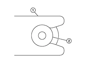
Do not twist the front wheel sensor harness when installing the front wheel sensor. Check that the grommet (2) is fully inserted to the bracket (1). Check that the front wheel sensor harness is not twisted after installation.
Front Sensor Rotor
Removal and Installation
Removal and Installation
The front wheel sensor rotor is an integral part of the wheel bearing and cannot be disassembled. Refer to Removal and Installation.
Rear Sensor Rotor
Removal and Installation
Removal and Installation
The rear wheel sensor rotor is an integral part of the wheel hub assembly and cannot be disassembled. Refer to Removal and Installation (Drum brake) or Removal and Installation (Disc brake).
Abs Actuator and Electric Unit (control Unit)
Exploded View
Exploded View
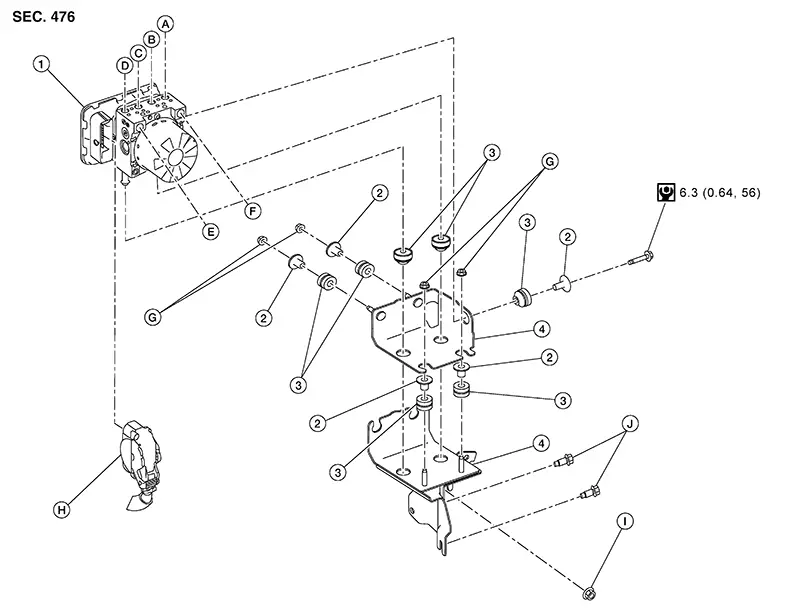
|
1. |
ABS actuator and electric unit (control unit) |
2. |
Insulator collar |
3. |
Insulator |
|
4. |
Bracket |
A. |
To rear (LH) brake caliper or wheel cylinder. Refer to Exploded View. |
B. |
To front (RH) brake caliper. Refer to Exploded View. |
|
C. |
To front (LH) brake caliper. Refer to Exploded View. |
D. |
To rear (RH) brake caliper or wheel cylinder. Refer to Exploded View. |
E. |
From master cylinder primary side. Refer to Exploded View. |
|
F. |
From master cylinder secondary side. Refer to Exploded View. |
G. |
Nut |
H. |
Harness connector |
|
I. |
Refer to Removal and Installation. |
J. |
Refer to Removal and Installation. |
Removal and Installation
Removal and Installation
REMOVAL
CAUTION:
-
To remove a brake tube, use a flare nut wrench to prevent the flare nuts and the brake tube from being damaged.
-
Do not remove the ABS actuator and electric unit (control unit) by holding the harness.

-
When removing components such as hoses, tubes/lines, etc., cap or plug openings to prevent fluid from spilling.
-
Do not swap ABS actuator and electric unit (control unit) between Nissan Sentra vehicles for any reason.
Perform the "ADDITIONAL SERVICE WHEN REPLACING ABS ACTUATOR AND ELECTRIC UNIT (CONTROL UNIT)". Refer to Description.
Remove the internal heat exchanger. Refer to Removal and Installation.
Disconnect the harness connector
(A) from the ABS actuator and electric unit (control unit). Follow
the procedure described below: 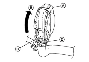 Push the
connector position assurance
(C). Move the lever (D) in the direction
(B) until the harness connector is unlocked. Disconnect the harness connector
from the ABS actuator and electric unit (control unit).
Push the
connector position assurance
(C). Move the lever (D) in the direction
(B) until the harness connector is unlocked. Disconnect the harness connector
from the ABS actuator and electric unit (control unit).
Loosen the brake tube flare nuts using a flare nut wrench and separate the brake tubes from the ABS actuator and electric unit (control unit). Refer to Exploded View and to Exploded View.
Separate the brake pipes from the clamps on the cowl.
Remove the bolts and the nut from the bracket. Refer to Exploded View.
Remove the ABS actuator and electric unit (control unit) with the brackets as an assembly.
If necessary, remove the nuts and the bolt from the brackets.
If necessary, remove the brackets from the ABS actuator and electric unit (control unit).
If necessary, remove the insulators and the insulator collars from the brackets.
INSTALLATION
If removed, install the insulators and the insulator collars to the brackets. Refer to Exploded View.
Note:
Do not swap ABS actuator and electric unit (control unit) between Nissan Sentra vehicles for any reason.
If removed, install the brackets to the ABS actuator and electric unit (control unit).
If removed, install the nuts and the bolt to the brackets.
Install the ABS actuator and electric
unit (control unit) with the brackets as an assembly using the following
procedure: 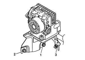 Position the ABS actuator and
electric unit (control unit) with the brackets in the Nissan Sentra vehicle. Tighten the nut and bolts to
the specified torque in the sequence shown.
Position the ABS actuator and
electric unit (control unit) with the brackets in the Nissan Sentra vehicle. Tighten the nut and bolts to
the specified torque in the sequence shown.
|
Nut and bolts |
: 21.1 N·m (2.2 kg-m, 16 ft-lb) |
CAUTION:
-
Do not apply excessive impact to the brackets.
-
Do not apply excessive impact to the ABS actuator and electric unit (control unit), such as dropping it.
-
Do not install the ABS actuator and electric unit (control unit) by holding the harness.
Install the brake tubes to the ABS actuator and electric unit (control unit). Refer to Exploded View and to Exploded View.
CAUTION:
To install a brake tube, use a flare nut crowfoot and a torque wrench.
Install the brake pipes to the clamps on the cowl.
Install the harness connector (A)
to the ABS actuator and electric unit (control unit). Follow the procedure
described below: 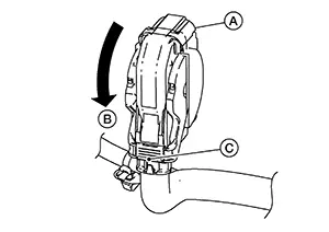 Connect the harness
connector
to the ABS actuator and electric unit (control unit). Move the lever (C) in the direction
(B) until the harness connector is locked.
Connect the harness
connector
to the ABS actuator and electric unit (control unit). Move the lever (C) in the direction
(B) until the harness connector is locked.
CAUTION:
After installing the harness connector to the ABS actuator and electric unit (control unit), make sure the harness connector is securely locked.
Install the internal heat exchanger. Refer to Removal and Installation.
Bleed air from the brake tubes. Refer to Bleeding Brake System.
Perform the "ADDITIONAL SERVICE WHEN REPLACING ABS ACTUATOR AND ELECTRIC UNIT (CONTROL UNIT)". Refer to Description.
Other materials:
Wiper & Washer. Service Data and Specifications (sds). Service Data and Specifications (sds). Specifications
Service Data and Specifications (sds). Specifications
Specifications
Specifications
WITH WASHER LEVEL SWITCH
Windshield washer fluid
capacity
4.2
(4 1/2 US qt, 3 3/4 Imp qt)
...
Front Brake Caliper Assembly
Exploded View
Exploded View
1.
Brake caliper body
2.
Bleeder valve
3.
...
U2141 Can Comm Err (tcm)
Dtc Description
DTC Description
DTC DETECTION LOGIC
DTC No.
CONSULT screen
terms
(Trouble
diagnosis content)
DTC detection condition
...