Nissan Sentra Service Manual: Removal and installation
Horn
Exploded view
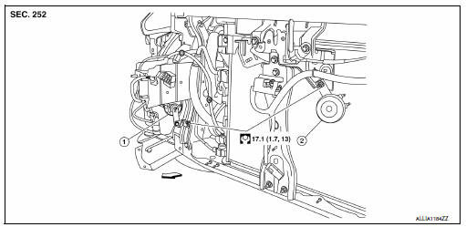
- Horn high
- Horn low
 Front
Front
Note:
Shown with the front fascia removed for clarity.
Removal and installation
Horn low
Removal
- Remove the core support cover. Refer to ext-23, "removal and installation".
- Disconnect the horn low harness connectors.
Note:
The harness connector locations prior to removal.
- Remove the horn nut and the horn low.
Installation
Installation is in the reverse order of removal.
Note:
Install the harness connector in the proper locations.
Horn high
Removal
- Partially remove the rh fender protector. Refer to ext-28, "fender protector : removal and installation - front fender protector".
- Disconnect the horn high harness connectors.
Note:
The harness connector locations prior to removal.
- Remove the horn nut and the horn high.
Installation
Installation is in the reverse order of removal.
Note:
Install the harness connector in the proper locations.
 Wiring diagram
Horn
Wiring diagram
...

Other materials:
Roof side molding
Exploded view
Roof side molding
Roof side molding clip
Roof panel
Body side outer panel
Adhesive tape
Removal and installation
REMOVAL
ROOF SIDE MOLDING
Release roof side molding rear side clip, using a suitable tool
(A).
Clip
Front
CAUTION:
Apply protective tape ...
Rear window defogger relay
Description
Power is supplied to the rear window defogger with BCM control.
Component Function Check
1. Check rear window defogger relay power supply circuit
Turn ignition switch ON.
Check that an operation noise of rear window defogger relay (located in
IPDM E/R) can be heard when
t ...
Windshield wiper and washer switch
Switch operation
Type A
Type B
The windshield wiper and washer operates when
the ignition switch is placed in the ON position.
Push the lever down to operate the wiper at the
following speed:
Intermittent (INT) — intermittent operation
can be adjusted by turning the knob A .
Lo ...
