Nissan Sentra B18 (2020-2025) Service Manual: Rear View Camera Image Signal Circuit
Diagnosis Procedure
-
CHECK CAMERA POWER SUPPLY CIRCUIT CONTINUITY
-
-
Ignition switch OFF.
-
Disconnect AV control unit connector and rear view camera connector.
-
Check continuity between AV control unit connector and rear view camera connector.
AV control unit
Rear view camera
Continuity
Connector
Terminal
Connector
Terminal
M93
39
B30
1
Yes
-
Check continuity between AV control unit connector and ground.
AV control unit
ŌĆö
Continuity
Connector
Terminal
M93
39
Ground
No
-
Is inspection result normal?
YES >>GO TO 2.
NO >>Repair or replace harness or connectors.
-
-
CHECK CAMERA POWER SUPPLY VOLTAGE
-
-
Connect AV control unit connector and rear view camera connector.
-
Ignition switch ON.
-
Shift the selector lever to R (reverse).
-
Check voltage between AV control unit connector and ground.
AV control unit
(ŌłÆ)
Condition
Voltage
(Approx.)
(+)
Connector
Terminal
M93
39
Ground
Selector lever is in ŌĆ£RŌĆØ.
6.0 V
-
Is inspection result normal?
YES >>GO TO 3.
NO >>Replace AV control unit. Refer to Removal and Installation.
-
-
CHECK CAMERA IMAGE SIGNAL CIRCUIT CONTINUITY
-
-
Ignition switch OFF.
-
Disconnect AV control unit connector and rear view camera connector.
-
Check continuity between AV control unit connector and rear view camera connector.
AV control unit
Rear view camera
Continuity
Connector
Terminal
Connector
Terminal
M93
40
B30
3
Yes
-
Check continuity between AV control unit connector and ground.
AV control unit
ŌĆö
Continuity
Connector
Terminal
M93
40
Ground
No
-
Is inspection result normal?
YES >>GO TO 4.
NO >>Repair or replace harness or connectors.
-
-
CHECK CAMERA GROUND CIRCUIT CONTINUITY
-
Check continuity between AV control unit connector and rear view camera connector.
AV control unit
Rear view camera
Continuity
Connector
Terminal
Connector
Terminal
M93
59
B30
2
Yes
Is inspection result normal?
YES >>GO TO 5.
NO >>Repair or replace harness or connectors.
-
-
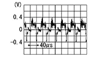
CHECK CAMERA IMAGE SIGNAL
-
-
Connect AV control unit connector and rear view camera connector.
-
Ignition switch ON.
-
Shift the selector lever to R (reverse).
-
Check signal between AV control unit connector and ground.
AV control unit
(ŌłÆ)
Condition
Reference value
(+)
Connector
Terminal
M93
40
Ground
Camera image displayed.
-
Is inspection result normal?
YES >>Replace AV control unit. Refer to Removal and Installation.
NO >>Replace rear view camera. Refer to Removal and Installation.
-
 Power Supply and Ground Circuit
Av Control Unit
Diagnosis Procedure
Diagnosis Procedure
CHECK FUSE
Check that the following fuse is not blown:
...

Other materials:
Seat Belt Warning Lamp System
System Description
System Description
SYSTEM DIAGRAM
System Description
The seat belt warning lamp (1) will remind the
driver if the driver or front passenger seat belt should be
buckled. The system works in conjunction with the occupant
classification system. Refer to System ...
Using the system
The NISSAN Voice Recognition system allows
hands-free operation of the Bluetooth® Phone
System.
If the vehicle is in motion, some commands may
not be available so full attention may be given to
vehicle operation.
Initialization
When the ignition switch is placed in the ON
position, NISSAN ...
On board diagnosis function
ON BOARD DIAGNOSIS ITEM
The on board diagnostic system has the following functions.
Diagnostic test mode
Function
Bulb check
MIL can be checked.
SRT status
ECM can read if SRT codes are set.
Malfunction warning
If ECM detects a malfunction, it illumina ...
