Nissan Sentra Service Manual: Rear door finisher
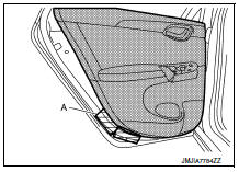
Exploded View
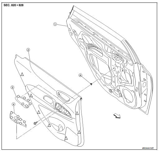
- Rear door panel
- Rear door finisher
- Inside door handle escutcheon
- Rear power window switch finisher
- Grommet
 Clip
Clip
 Pawl
Pawl
 Front
Front
Removal and Installation
CAUTION:
- When removing, always use a suitable tool that is made of plastic to prevent damage to the parts.
- Do not damage the door panel.
REMOVAL
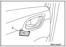
- Remove inside door handle escutcheon.
- Apply protective tape (A) to protect the component from damage as shown.
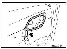
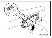
- Insert a suitable tool (A) as shown between inside door handle escutcheon and inside door handle.
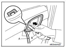
- With suitable tool (A) in position, insert a second suitable tool (B) as shown, then release pawl as shown.
 Pawl
Pawl
- Pull upward on the inside door handle escutcheon as shown to release the pawls on the upper portion of inside door handle escutcheon.
 Pawl
Pawl
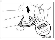
- Press down on the inside door handle escutcheon as shown to release the pawls on the lower portion of inside door handle escutcheon.
 Pawl
Pawl
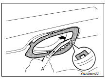
- Insert a suitable tool (A) as shown to release the remaining pawl and remove.
 Pawl
Pawl
- Remove rear power window switch finisher. Refer to PWC-72, "Removal and Installation".
- Remove rear door finisher.
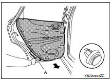
- Remove rear door finisher screw (A).
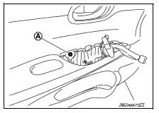
- Apply protective tape (A) to protect the component from damage as shown.
- Release rear door finisher clips using a suitable tool (A) as shown.
 Clip
Clip
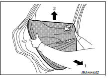
Remove rear door finisher as shown.
INSTALLATION
Installation is in the reverse order of removal.
CAUTION:
When installing, check that clips are accurately aligned with the holes on the door panel, then press in.
 Front door finisher
Exploded View
Front door panel
Front door finisher
Inside door handle escutcheon
Main power window and door lock/
unlock switch finisher
Door mirror corner finisher
Grommet
...
 Body side trim
Exploded View
Rear body side welt
Front body side welt
Tether clip
Front pillar finisher
Metal clip
Dash clip
Dash side finisher
Harness protector
Front kicking plate inner
C ...
Other materials:
Refrigerant
Description
CONNECTION OF SERVICE TOOLS AND EQUIPMENT
Shut-off valve
A/C service valve
Recovery/recycling/recharging
equipment
Refrigerant container (HFC-134a)
Weight scale (J-39650)
Vacuum pump (J-39649)
Manifold gauge set (J-39183)
Preferred (best) method
Alternativ ...
Dtc/circuit diagnosis
U1000 can comm circuit
DTC Logic
DTC DETECTION LOGIC
CONSULT Display
DTC Detection Condition
Possible Cause
CAN COMM CIRCUIT
[U1000]
AV control unit is not transmitting or receiving
CAN communication signal for 2 seconds or
more.
CAN communication system.
...
Recommended chemical products and sealants
Refer to the following chart for help in selecting the appropriate chemical
product or sealant.
Product Description
Purpose
Nissan North America
Part No. (USA)
Nissan Canada Part
No. (Canada)
Aftermarket Crossreference
Part Nos.
1
Rear View Mirror ...
