Nissan Sentra B18 (2020-2025) Service Manual: Rear Door
Exploded View
Exploded View
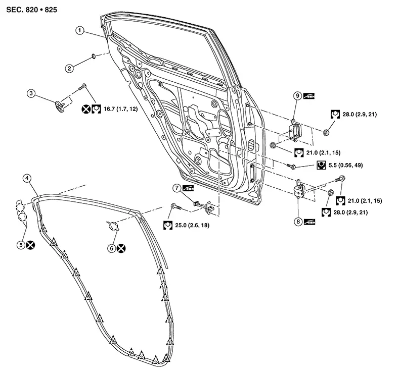
|
1. |
Rear door panel |
2. |
Grommet |
3. |
Door striker |
|
4. |
Weather-strip |
5. |
Weather-strip rear cover |
6. |
Weather-strip front cover |
|
7. |
Door check link |
8. |
Rear door lower hinge |
9. |
Rear door upper hinge |
|
|
Pawl |
|
Clip |


Door Assembly
Removal and Installation
Removal and Installation
CAUTION:
-
Use two people when removing or installing the rear door due to its heavy weight.
-
When removing and installing rear door assembly, support rear door using a suitable tool.
REMOVAL
Remove rear
door harness grommet (1).
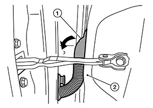
Release and pull harness out from the body side (2).
Disconnect the harness connectors from rear door.
Remove rear
door check link bolt (A) from body side (1).
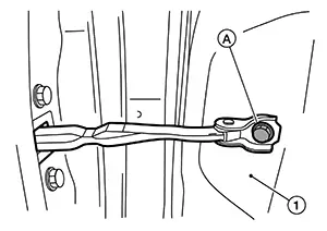
Remove rear door hinge nuts (door side) and rear door assembly.
INSTALLATION
Installation is in the reverse order of removal.
CAUTION:
-
Apply anticorrosive agent where necessary.
-
After installation, check rear door open/close and lock/unlock operation.
-
After installation, perform the rear door adjustment procedure. Refer to Adjustment.
Adjustment
Adjustment
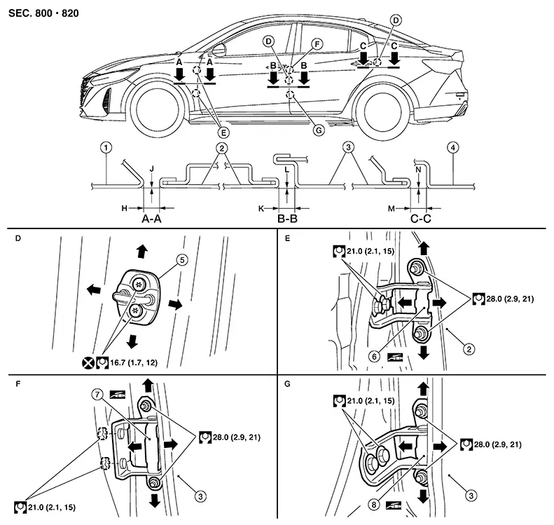
|
1. |
Front fender |
2. |
Front door |
3. |
Rear door |
|
4. |
Body side outer |
5. |
Door striker |
6. |
Front door hinge |
|
7. |
Rear door upper hinge |
8. |
Rear door lower hinge |
Check the clearance and surface height between front door and each part by visual inspection and tactile feel.
If the clearance and the surface height are out of specification, adjust them according to the adjustment procedure.
Unit: mm (in)|
Section |
Item |
Measurement |
Standard |
|---|---|---|---|
|
A – A |
H |
Clearance |
4.0 ± 1.0 (0.16 ± 0.04) |
|
J |
Surface height |
0.0 ± 1.0 (0.0 ± 0.04) |
|
|
B – B |
K |
Clearance |
4.2 ± 1.0 (0.17 ± 0.04) |
|
L |
Surface height |
0.0 ± 1.0 (0.0 ± 0.04) |
|
|
C – C |
M |
Clearance |
4.0 ± 1.0 (0.16 ± 0.04) |
|
N |
Surface height |
0.0 ± 1.0 (0.0 ± 0.04) |
Remove center pillar lower finisher. Refer to Removal and Installation.
Loosen rear door hinge nuts (door side).
Adjust the surface height of rear door according to specifications provided.
Temporarily tighten rear door hinge nuts (door side).
Loosen rear door hinge nuts and bolts (body side).
Raise rear door at rear end to adjust clearance of rear door according to the specifications provided.
After adjustment tighten bolts and nuts to the specified torque.
CAUTION:
-
Check rear door hinge rotating point for poor lubrication. If necessary, apply a suitable multi-purpose grease.
-
After adjusting, apply touch-up paint (body color) to the head of rear door hinge bolts and nuts.
Install center pillar lower finisher. Refer to Removal and Installation.
Door Striker
Removal and Installation
Removal and Installation
REMOVAL
Remove bolts.
Remove rear door striker.
INSTALLATION
Installation is in the reverse order of removal.
CAUTION:
-
Do not reuse rear door striker bolts.
-
After installation, check rear door open/close operation. If necessary, adjust the door striker. Refer to Adjustment.
Adjustment
Adjustment
Loosen door striker bolts.
Adjust door
striker so that it becomes parallel with front door lock insertion
direction.
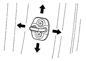
Tighten door striker bolts to specification. Refer to Exploded View.
Door Hinge
Removal and Installation
Removal and Installation
REMOVAL
Remove rear door assembly. Refer to Removal and Installation.
Remove center pillar lower finisher (rear door lower hinge only). Refer to Removal and Installation.
Remove rear door hinge bolts and nuts and rear door hinge.
INSTALLATION
Installation is in the reverse order of removal.
CAUTION:
-
Apply anticorrosive agent onto the hinge mating surface.
-
After installation, check rear door open/close and lock/unlock operation.
-
After installation, perform the rear door adjustment procedure. Refer to Adjustment.
Door Check Link
Removal and Installation
Removal and Installation
REMOVAL
Remove rear door finisher. Refer to Removal and Installation.
Partially remove vapor barrier (front).
Remove door check link bolt from (body side).
Remove door check link bolts from (door side).
Remove door check link through hole in door panel.
INSTALLATION
Installation is in the reverse order of removal.
CAUTION:
-
After installation, check rear door open/close and lock/unlock operation.
-
Check rear door check link rotating point for poor lubrication. If necessary, apply a suitable multi-purpose grease.
Other materials:
U1010 Control Unit(can)
Dtc Description
DTC Description
DTC DETECTION LOGIC
DTC No.
CONSULT screen
terms
(Trouble
diagnosis content)
DTC detection condition
...
Dtc/circuit Diagnosis
Eco Mode Switch
Component Function Check
Component Function Check
CHECK ECO MODE SWITCH OPERATION
Ignition switch ON.
Check ECO mode indicator turns ON/OFF
on combination meter when turn ECO mode switch
O ...
Diagnosis System (intelligent Key Unit)
Consult Function (hands Free Module)
CONSULT Function
(HANDS FREE MODULE)
Intelligent Key unit
Refer to CONSULT Function
(HANDS FREE MODULE).
...