Nissan Sentra B18 (2020-2025) Service Manual: Rear Brake Assembly
Exploded View
Exploded View
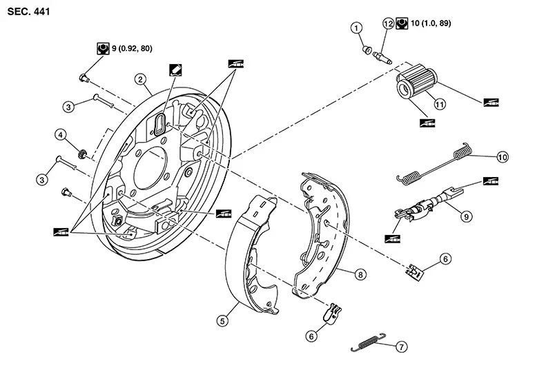
|
1. |
Bleeder Cap |
2. |
Back plate |
3. |
Shoe hold pin |
|
4. |
Plug |
5. |
Brake shoe (leading side) |
6. |
Retainer |
|
7. |
Return spring (lower side) |
8. |
Brake shoe (trailing side) |
9. |
Adjuster |
|
10. |
Adjuster spring |
11. |
Wheel cylinder |
12. |
Bleeder Valve |
|
|
Molyguard GS 2039 or Kluber Syntheso GLEP 1 grease |
|
Silicone sealant |


Removal and Installation
Removal and Installation
Warning:
Clean dust on the rear brake assembly using a vacuum dust collector to minimize the hazard of airborne particles or other material.
CAUTION:
-
Do not depress the brake pedal while removing the brake drum because the pistons may pop out.
-
Do not drop the removed parts.
-
Do not spill or splash brake fluid on painted surfaces. Brake fluid may seriously damage paint. Wipe it off immediately and wash with water if it gets on a painted surface.
-
Do not spill or splash brake fluid on the brake drum.
-
Do not bend, twist, or pull the brake hoses and piping.
-
Do not reuse drained brake fluid.

When removing components such as hoses, tubes/lines, etc., cap or plug openings to prevent fluid from spilling.
REMOVAL
Release the parking brake.
Remove the rear wheel and tire using power tools. Refer to Removal and Installation.
Remove the brake drum. Refer to Removal and Installation.
While
pushing the retainer (1), remove the shoe hold pin, then remove the
retainer. 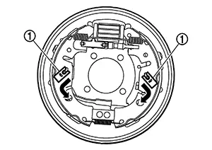
CAUTION:
Do not damage the wheel cylinder boot.
Press the
rear cable spring against the spring tension to separate the rear
parking brake cable (1) from the clamp (A). Remove the brake shoe
[trailing side (2)]. 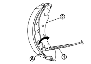
CAUTION:
-
Do not bend the rear parking cable (LH/RH).
-
Do not damage the wheel cylinder boot.
-
Do not drop the brake shoe.
Remove the brake shoes, the springs, and the adjuster.
-
LH
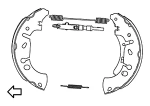

: Front
-
RH
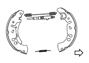
: Front
Loosen the flare nut using a flare nut wrench. Separate the brake tube from the wheel cylinder. Refer to Exploded View.
Remove the bolts and the wheel cylinder from the back plate. Refer to Exploded View.
CAUTION:
-
Do not damage the back plate.
-
Do not damage the wheel cylinder.
Remove the plugs.
Remove the wheel hub assembly, then remove the back plate. Refer to Exploded View.
INSPECTION AFTER REMOVAL
Check the following items and replace parts if necessary:
-
Check the brake shoe lining surface for excessive wear, damage, and peeling.
-
Check the brake shoe sliding surface for excessive wear and damage.
-
Check each spring for settling, excessive wear, damage, and rust.
-
Check the adjuster for a lack of smoothness, excessive wear, damage, and rust.
-
Check the back plate for damage, cracks, and deformation.
-
Check the wheel cylinder for cracks, damage, and leaking brake fluid.
-
Check the brake drum for excessive wear, cracks, and damage.
-
Check the rear brake assembly parts for excessive wear, damage, and rust.
INSTALLATION
Install the back plate and the wheel hub assembly. Refer to Exploded View.
Install the plugs.
Remove silicone sealant completely from the back plate. Refer to Exploded View.
CAUTION:
-
Do not allow old silicone sealant, moisture, oil, or foreign material, to remain on the silicone sealant application surface.
-
Check that the mounting surface is not damaged.
Apply a continuous bead of silicone sealant to the back plate.
Install the wheel cylinder to the back plate. Tighten the bolts to the specified torque.
Install the brake tube to the wheel cylinder. Tighten the brake tube flare nut to the specified torque using a flare nut crowfoot and a torque wrench. Refer to Exploded View.
Apply
Molyguard GS 2039 or Kluber Syntheso GLEP 1 grease to the matching
surfaces (A) between the back plate (1) and the brake shoes. 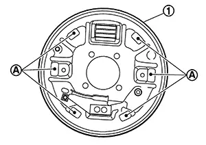
Apply Molyguard GS 2039 or Kluber Syntheso GLEP 1 grease to the matching surfaces between the adjuster and the brake shoes.
Install the brake shoes, the springs, and the adjuster.
Install the shoe hold down pins and the retainers.
Install the rear parking brake cable to the brake shoe (trailing side).
Verify the rear brake assembly parts are installed properly as shown.
-
LH
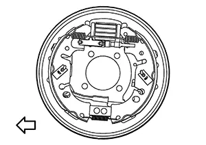
: Front
-
RH
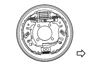
: Front
Adjust the position of the brake shoes to fit in the brake drum using a suitable tool. Shorten or lengthen the adjuster as necessary.
Install the brake drum. Refer to Removal and Installation.
Install the wheel and tire. Refer to Removal and Installation.
Refill with new brake fluid and bleed air from the brake system. Refer to Bleeding Brake System.
Depress the brake pedal several times and perform the inspection after installation.
INSPECTION AFTER INSTALLATION
Inspect the parking brake lever stroke. Refer to Inspection (HAND LEVER WITH REAR DRUM BRAKES) or to Inspection (FOOT PEDAL WITH REAR DRUM BRAKES). If the parking brake lever stroke does not meet the standards, perform the adjustment after installation.
Rotate the brake drum and check for drag. If any drag is found, perform the adjustment after installation.
ADJUSTMENT AFTER INSTALLATION
If the parking brake lever stroke does not meet the standards, adjust the parking brake lever stroke. Refer to Adjustment (HAND LEVER WITH REAR DRUM BRAKES) or to Adjustment (FOOT PEDAL WITH REAR DRUM BRAKES).
If any brake drum drag is found, perform the following procedure: Remove the brake shoes. Push the pistons into the wheel cylinder.
CAUTION:
Push both pistons simultaneously.
Install the brake shoes. Adjust the brake shoe clearance. Rotate the brake drum and check for drag again. If any drag is found, replace rear brake assembly parts if necessary.Burnish the contact surfaces between the brake shoes and the brake drum after replacing the brake shoes or if a soft pedal occurs at very low mileage. Refer to Periodic Maintenance Operation.
Other materials:
B20ce-15 Hl (hi) Lh Pwr Sply Circ
Dtc Description
DTC Description
DTC DETECTION LOGIC
DTC No.
CONSULT screen items
(Trouble diagnosis content)
DTC detection condition
...
P0078 Evt Control Solenoid Valve
Dtc Description
DTC Description
DTC DETECTION LOGIC
DTC
CONSULT screen terms
(Trouble diagnosis
content)
DTC detection
condition
...
B2033-4a Dongle Ng
Dtc Description
DTC Description
DTC DETECTION LOGIC
DTC No.
CONSULT screen items
(Trouble diagnosis
content)
DTC detection condition
...