Nissan Sentra Service Manual: Radiator
Exploded View
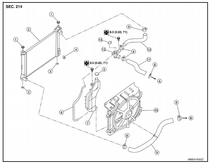
- Mounting rubber (upper)
- Radiator
- Mounting rubber (lower)
- Radiator drain plug
- Reservoir tank cap
- Reservoir tank hose
- Reservoir tank
- Clamp
- Radiator hose (lower)
- Fan shroud and motor assembly
- Radiator hose (upper)
- Filler neck hose
- Filler neck
- Radiator filler cap
- To water outlet
- To water inlet
WARNING:
Do not remove the radiator cap when the engine is hot. Serious burns could occur from high-pressure engine coolant escaping from the radiator. Wrap a thick cloth around the cap. Slowly push down and turn it a quarter turn to allow built-up pressure to escape. Carefully remove the cap by pushing it down and turning it all the way.
NOTE:
When removing components such as hoses, tubes/lines, etc., cap or plug openings to prevent fluid from spilling.
Removal and Installation
REMOVAL
- Disconnect the negative battery terminal. Refer to PG-52, "Removal and Installation".
- Remove fan shroud and motor assembly. Refer to CO-17, "Removal and Installation".
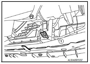
- Remove radiator cap, open radiator drain plug and drain engine coolant from radiator. Refer to CO-12, "Changing Engine Coolant".
CAUTION:
- Perform this step when the engine is cold.
- Do not spill engine coolant on the drive belt.
- Remove radiator hose (lower). Refer to CO-15, "Exploded View".
- Remove condenser bolts from radiator.
- Remove the radiator from the vehicle.
CAUTION:
Be careful not to damage radiator core and condenser assembly core.
INSTALLATION
Installation is in the reverse order of removal.
- After installation, refill engine coolant and check for leaks. Refer to CO-12, "Changing Engine Coolant" and CO-11, "System Inspection".
NOTE:
When installing radiator core support (upper), check that both upper and lower mounts of radiator and air conditioner condenser are inserted in the mounting holes of radiator core support (upper, lower).
CAUTION:
Do not spill engine coolant in engine compartment. Use a shop cloth to absorb engine coolant.
Inspection
INSPECTION AFTER INSTALLATION
- Check that the reservoir tank cap is tightened.
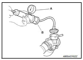
- Check for leaks of engine coolant using Tool (B) and suitable tool
(A). Refer to CO-11, "System Inspection".
Tool number : EG17650301 (J-33984-A)
Testing pressure : Refer to CO-28, "Radiator".
WARNING:
Do not remove the radiator cap when the engine is hot. Serious burns could occur from high pressure engine coolant escaping from the radiator.
CAUTION:
Higher pressure than specified may cause radiator damage.
- Start and warm up the engine. Visually check that there are no engine coolant or CVT fluid leaks.

 Cooling fan
Component
Fan shroud and motor assembly
WARNING:
Do not remove the radiator cap when the engine is hot. Serious burns
could occur from high-pressure
engine coolant escaping from the ra ...
Other materials:
Ecu diagnosis information
Audio unit
Reference value
TERMINAL LAYOUT
PHYSICAL VALUES
Bose speaker amp
Reference value
TERMINAL LAYOUT
PHYSICAL VALUES
BluetoothВ® control unit
Reference value
TERMINAL LAYOUT
PHYSICAL VALUES
...
Interior room lamp
Removal and installation
Removal
Insert a suitable tool into the gap between the headlining and the
interior room lamp and release the interior
room lamp.
Disconnect the harness connector from the interior room lamp.
Installation
Installation is in the reverse order of removal.
Bul ...
P014C, P014D, P015A, P015B A/F Sensor 1
DTC Logic
DTC DETECTION LOGIC
To judge the malfunction of A/F sensor 1, this diagnosis measures response
time of the A/F signal computed
by ECM from the A/F sensor 1 signal. The time is compensated by engine operating
(speed and load), fuel
feedback control constant, and the A/F sensor 1 tem ...
