Nissan Sentra Owners Manual: Push-Button Ignition Switch (if so equipped)
| WARNING Do not operate the push-button ignition switch while driving the vehicle except in an emergency. (The engine will stop when the ignition switch is pushed 3 consecutive times in quick succession or the ignition switch is pushed and held for more than 2 seconds.) If the engine stops while the vehicle is being driven, this could lead to a crash and serious injury. |
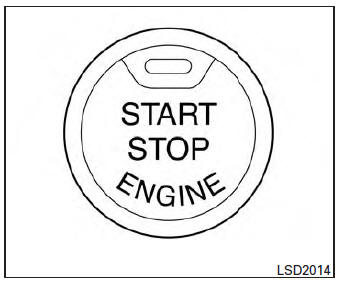
When the ignition switch is pushed without depressing the brake pedal or the clutch pedal (MT), the ignition switch position will illuminate as follows:
Push center
- once to change to ACC.
- two times to change to ON.
- three times to return to OFF.
The ignition switch will automatically return to the LOCK position when any door is either opened or closed with the switch in the OFF position.
The ignition lock is designed so that the ignition switch position cannot be switched to OFF until the shift lever is moved to the P (Park) position or N (Neutral) position (MT).
When the ignition switch cannot be pushed toward the OFF position, proceed as follows:
- Move the shift lever into the P (Park) position or N (Neutral) position (MT).
- Push the ignition switch. The ignition switch position will change to the ON position.
- Push the ignition switch again to the OFF position.
The shift lever can be moved from the P (Park) position if the ignition switch is in the ON position and the brake pedal is depressed.
If the battery of the vehicle is discharged, the push-button ignition switch cannot be moved from the LOCK position.
Some indicators and warnings for operation are displayed in the meter. See “Warning/indicator lights and audible reminders” in the “Instruments and controls” section.
- Operating range
- Push-button ignition switch positions
- Emergency engine shut off
- NISSAN Intelligent Key® battery discharge
- NISSAN vehicle immobilizer system
 NISSAN vehicle immobilizer system
The NISSAN Vehicle Immobilizer system will not
allow the engine to start without the use of the
registered key.
If the engine fails to start using a registered key
(for example, when interferenc ...
 Operating range
The Intelligent Key functions can only be used
when the Intelligent Key is within the specified
operating range.
When the Intelligent Key battery is almost discharged
or strong radio waves a ...
Other materials:
Front combination lamp
Exploded View
Large cover (not serviceable)
Small cover (not serviceable)
Front combination lamp
Halogen lamp bulb (high beam)
Turn signal lamp bulb
Turn signal lamp bulb socket
LED harness connector
Halogen lamp bulb (high beam)
harness connector
Halogen lamp bulb (low bea ...
Windshield glass
Exploded View
Windshield glass molding
Spacer
Rubber dam
Windshield glass
Windshield insulator
Front pillar finisher
Instrument panel
Cowl top cover
Roof panel
Cowl top
Body side outer
Headlining
Adhesive
12 +2.0 mm (0.5 +0.08 in)
7 +2.0 mm (0.3 +0.08 in)
...
Inside key antenna
Console
CONSOLE : Removal and Installation
REMOVAL
Remove the shift selector finisher. Refer to IP-17, "Removal and
Installation".
Remove the inside key antenna (console) screws (A) and inside
key antenna (console) (1).
INSTALLATION
Installation is in the reverse order ...
