Nissan Sentra B18 (2020-2025) Service Manual: Precautions
Precaution for Supplemental Restraint System (srs) "air Bag" and "seat Belt Pre-Tensioner"
The Supplemental Restraint System such as “AIR BAG” and “SEAT BELT PRE-TENSIONER”, used along with a front seat belt, helps to reduce the risk or severity of injury to the driver and front passenger for certain types of collisions.
Information necessary to service the system safely is included in the “SRS AIR BAG” and “SEAT BELT” sections of this Service Manual.
Warning:
Always observe the following items for preventing accidental activation:
-
To avoid rendering the SRS inoperative, which could increase the risk of personal injury or death in the event of a collision that would result in air bag inflation, it is recommended that all maintenance and repair be performed by an authorized NISSAN/INFINITI dealer.
-
Improper repair, including incorrect removal and installation of the SRS, can lead to personal injury caused by unintentional activation of the system. For removal of Spiral Cable and Air Bag Module, see “SRS AIR BAG”.
-
Never use electrical test equipment on any circuit related to the SRS unless instructed to in this Service Manual. SRS wiring harnesses can be identified by yellow and/or orange harnesses or harness connectors.
PRECAUTIONS WHEN USING POWER TOOLS (AIR OR ELECTRIC) AND HAMMERS
Warning:
Always observe the following items for preventing accidental activation:
-
When working near the Air Bag Diagnosis Sensor Unit or other Air Bag System sensors with the ignition/power switch ON or engine running, never use air or electric power tools or strike near the sensor(s) with a hammer. Heavy vibration could activate the sensor(s) and deploy the air bag(s), possibly causing serious injury.
-
When using air or electric power tools or hammers, always switch the ignition/power switch OFF, disconnect the 12V battery or batteries, and wait at least 3 minutes before performing any service.
PRECAUTIONS WHEN USING POWER TOOLS (AIR OR ELECTRIC) AND HAMMERS
Warning:
-
When working near the Air Bag Diagnosis Sensor Unit or other Air Bag System sensors with the Ignition ON or engine running, DO NOT use air or electric power tools or strike near the sensor(s) with a hammer. Heavy vibration could activate the sensor(s) and deploy the air bag(s), possibly causing serious injury.
-
When using air or electric power tools or hammers, always switch the Ignition OFF, disconnect the battery or batteries, and wait at least three minutes before performing any service.
Precaution for Procedure Without Cowl Top Cover
When performing the procedure after removing cowl top cover, cover the lower end of windshield with urethane, etc. to prevent damage to windshield.
Service Notice or Precautions for Manual Transaxle
CAUTION:
-
Do not reuse CSC (Concentric Slave Cylinder). Because CSC slides back to the original position every time when removing transaxle assembly. At this timing, dust on the sliding parts may damage a seal of CSC and may cause clutch fluid leakage. Refer to Removal and Installation.
-
Do not reuse transaxle gear oil, once it has been drained.
-
Check oil level or replace gear oil with Nissan Sentra vehicle on level surface.
-
During removal or installation, keep inside of transaxle clear of dust or dirt.
-
Check for the correct installation status prior to removal or disassembly. If matching marks are required, be certain they never interfere with the function of the parts they are applied.
-
In principle, tighten bolts or nuts gradually in several steps working diagonally from inside to outside. If tightening sequence is specified, use it.
-
Do not damage sliding surfaces and mating surfaces.
Liquid Gasket
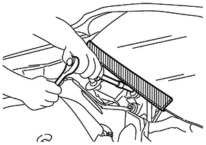
REMOVAL OF LIQUID GASKET SEALING
-
After removing the bolts and nuts, separate the mating surface and remove the liquid gasket using Tool (A).
Tool Number (A):
KV10111100 (NI-37228)
CAUTION:
Be careful not to damage the mating surfaces.
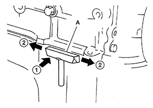
-
In areas where the cutter is difficult to use, use a plastic hammer to lightly tap (1) the cutter where the liquid gasket is applied. Use a plastic hammer to slide (2) the cutter by tapping on the side.
CAUTION:
Do not damage the mating surfaces.
LIQUID GASKET APPLICATION PROCEDURE
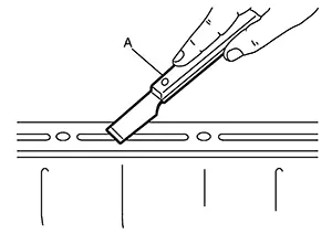
-
Using suitable tool (A), remove old liquid gasket adhering to the liquid gasket application surface and the mating surface.
-
Remove liquid gasket completely from the groove of the liquid gasket application surface, mounting bolts, and bolt holes.
-
-
Wipe the liquid gasket application surface and the mating surface with white gasoline (lighting and heating use) to remove adhering moisture, grease and foreign materials.
-
Attach liquid gasket tube using suitable tool.
Use Genuine Liquid Gasket or equivalent.
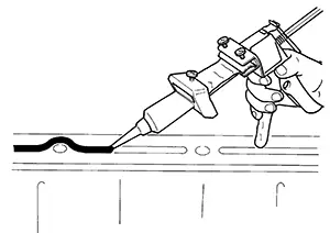
-
Apply liquid gasket without gaps to the specified location according to the specified dimensions.
-
If there is a groove for liquid gasket application, apply liquid gasket to the groove.
-
As for bolt holes (B), normally apply liquid gasket inside the holes. Occasionally, it should be applied outside the holes. Check to read the text of this manual.
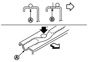
(A)
: Groove

: Inside
-
Within five minutes of liquid gasket application, install the mating component.
-
If liquid gasket protrudes, wipe it off immediately.
-
Do not retighten mounting bolts or nuts after the installation.
-
After 30 minutes or more have passed from the installation, fill engine oil and engine coolant.
CAUTION:
If there are specific instructions in this manual, observe them.
-
 Precaution
...
 Preparation
...
Other materials:
Sensor power supply 2 circuit
Description
ECM supplies a voltage of 5.0 V to some of the sensors systematically divided
into 2 groups, respectively.
Accordingly, when a short circuit develops in a sensor power source, a
malfunction may occur simultaneously
in the sensors belonging to the same group as the shorted-circui ...
How to Erase Permanent Dtc
Description
Description
WHEN A DTC IS STORED IN TCM
When a DTC is stored in TCM and MIL is ON, a permanent DTC is
erased with MIL shutoff if the same malfunction is not detected after performing
the driving pattern for MIL shutoff three times in a raw.
Note:
The following timing ...
B0012-55 Active Vent
Dtc Description
DTC Description
DTC DETECTION LOGIC
DTC No.
CONSULT screen items
(Trouble diagnosis
content)
DTC Detection Condition
...
