Nissan Sentra Service Manual: Precaution
Precaution for supplemental restraint system (SRS) "air bag" and "seat belt pre-tensioner"
The Supplemental Restraint System such as “AIR BAG” and “SEAT BELT PRE-TENSIONER”, used along with a front seat belt, helps to reduce the risk or severity of injury to the driver and front passenger for certain types of collision. Information necessary to service the system safely is included in the SR and SB section of this Service Manual.
WARNING:
- To avoid rendering the SRS inoperative, which could increase the risk of personal injury or death in the event of a collision which would result in air bag inflation, all maintenance must be performed by an authorized NISSAN/INFINITI dealer.
- Improper maintenance, including incorrect removal and installation of the SRS, can lead to personal injury caused by unintentional activation of the system. For removal of Spiral Cable and Air Bag Module, see the SR section.
- Do not use electrical test equipment on any circuit related to the SRS unless instructed to in this Service Manual. SRS wiring harnesses can be identified by yellow and/or orange harnesses or harness connectors.
PRECAUTIONS WHEN USING POWER TOOLS (AIR OR ELECTRIC) AND HAMMERS
WARNING:
- When working near the Airbag Diagnosis Sensor Unit or other Airbag System sensors with the Ignition ON or engine running, DO NOT use air or electric power tools or strike near the sensor(s) with a hammer. Heavy vibration could activate the sensor(s) and deploy the air bag(s), possibly causing serious injury.
- When using air or electric power tools or hammers, always switch the Ignition OFF, disconnect the battery and wait at least three minutes before performing any service.
Precaution for work
- When removing or disassembling each component, be careful not to damage or deform it. If a component may be subject to interference, be sure to protect it with a shop cloth.
- When removing (disengaging) components with a screwdriver or similar tool, be sure to wrap the component with a shop cloth or vinyl tape to protect it.
- Protect the removed parts with a shop cloth and prevent them from being dropped.
- Replace a deformed or damaged clip.
- If a part is specified as a non-reusable part, always replace it with a new one.
- Be sure to tighten bolts and nuts securely to the specified torque.
- After installation is complete, be sure to check that each part works properly.
- Follow the steps below to clean components:
Water soluble dirt:
- Dip a soft cloth into lukewarm water, wring the water out of the cloth and wipe the dirty area.
- Then rub with a soft, dry cloth.
Oily dirt:
- Dip a soft cloth into lukewarm water with mild detergent (concentration: within 2 to 3%) and wipe the dirty area.
- Then dip a cloth into fresh water, wring the water out of the cloth and wipe the detergent off.
- Then rub with a soft, dry cloth.
Do not use organic solvent such as thinner, benzene, alcohol or gasoline.
For genuine leather seats, use a genuine leather seat cleaner.
Working with HFC -134a (r-134a)
WARNING:
- CFC-12 (R-12) refrigerant and HFC-134a (R-134a) refrigerant are not compatible. If the refrigerants are mixed compressor failure is likely to occur. Refer to HA-25, "Inspection". To determine the purity of HFC-134a (R-134a) in the vehicle and recovery tank, use Refrigerant Recovery/Recycling Recharging equipment and Refrigerant Identifier.
- Use only specified oil for the HFC-134a (R-134a) A/C system and HFC-134a (R-134a) components. If oil other than that specified is used, compressor failure is likely to occur.
- The specified HFC-134a (R-134a) oil rapidly absorbs moisture from the atmosphere. The following handling precautions must be observed:
- When removing refrigerant components from a vehicle, immediately cap (seal) the component to minimize the entry of moisture from the atmosphere.
- When installing refrigerant components to a vehicle, do not remove the caps (unseal) until just before connecting the components. Connect all refrigerant loop components as quickly as possible to minimize the entry of moisture into system.
- Only use the specified oil from a sealed container. Immediately reseal containers of oil. Without proper sealing, oil will become moisture saturated and should not be used.
- Avoid breathing A/C refrigerant and oil vapor or mist. Exposure
may irritate eyes, nose and throat.
Remove HFC-134a (R-134a) from the A/C system using certified service equipment meeting requirements of SAE J2210 [HFC-134a (R-134a) recycling equipment], or J2209 [HFC-134a (R-134a) recycling equipment], If accidental system discharge occurs, ventilate work area before resuming service. Additional health and safety information may be obtained from refrigerant and oil manufacturers.
- Do not allow A/C oil to come in contact with styrofoam parts. Damage may result.
CONTAMINATED REFRIGERANT
If a refrigerant other than pure HFC-134a (R-134a) is identified in a vehicle, your options are:
- Explain to the customer that environmental regulations prohibit the release of contaminated refrigerant into the atmosphere.
- Explain that recovery of the contaminated refrigerant could damage your service equipment and refrigerant supply.
- Suggest the customer return the vehicle to the location of previous service where the contamination may have occurred.
- If you choose to perform the repair, recover the refrigerant using only
dedicated equipment and containers.
Do not recover contaminated refrigerant into your existing service equipment. If your facility does not have dedicated recovery equipment, you may contact a local refrigerant product retailer for available service.
This refrigerant must be disposed of in accordance with all federal and local regulations. In addition, replacement of all refrigerant system components on the vehicle is recommended.
- If the vehicle is within the warranty period, the air conditioner warranty is void. Please contact NISSAN Customer Affairs for further assistance.
Precaution for service equipment
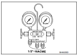
MANIFOLD GAUGE SET
Be certain that the gauge face indicates R-134a or 134a. Make sure the gauge set has 1/2″-16 ACME threaded connections for service hoses. Confirm the set has been used only with refrigerant HFC- 134a (R-134a) along with specified oil.

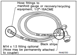
SERVICE HOSES
Be certain that the service hoses display the markings described (colored hose with black stripe). All hoses must include positive shutoff devices (either manual or automatic) near the end of the hoses opposite the manifold gauge.

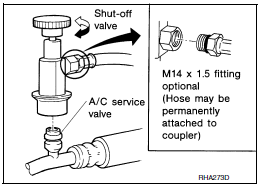
Service couplers
Do not attempt to connect HFC-134a (R-134a) service couplers to a CFC-12 (R-12) A/C system. The HFC-134a (R-134a) couplers will not properly connect to the CFC-12 (R-12) system. However, if an improper connection is attempted, discharging and contamination may occur.


 Preparation
Special service tool
The actual shape of the tools may differ from those illustrated here.
Commercial service tool
...
Other materials:
Trunk room trim
Exploded View
Trunk floor trim
Trunk front floor spacer (LH)
Trunk side finisher (LH)
Reflector box assembly*
Trunk rear plate
Trunk side finisher (RH)
Trunk front floor spacer (RH)
Clip
Pawl
Trunk rear plate
TRUNK REAR PLATE : Removal and Installation
REMOVAL
Remove ...
Water hose
Exploded View
Water outlet
Heater thermostat assembly
Hose clamp
CVT oil warmer
Water hose
To thermostat housing
To engine oil cooler
: Always replace after every
disassembly.
: NВ·m (kg-m, ft-lb)
Removal and Installation
REMOVAL
WARNING:
Do not remove the radi ...
General Precautions
Always use a 12 volt battery as power source.
Do not attempt to disconnect battery cables while engine is
running.
Before connecting or disconnecting the ECM harness connector,
turn ignition switch OFF and disconnect negative battery
cable. Failure to do so may damage the ECM because
...

