Nissan Sentra Service Manual: Parking brake system
Inspection and Adjustment
INSPECTION
Lever Stroke
-
Operate the parking brake lever with a force of 196 N (20.0 kg-f, 44.1 lb-f). Check that the lever stroke is within the specified number of notches. (Check it by listening to the clicks of the ratchet.)
Number of notches : Refer to PB-13, "Parking Brake Control".
-
When brake warning lamp turns ON, check that the lever stroke is within the specified number of notches.
(Check it by listening to the clicks of the ratchet.)
Number of notches : Refer to PB-13, "Parking Brake Control".
Inspect Components
-
Make sure that the attachment conditions (looseness, backlash, etc.) of each component are normal.
-
Check the following:
-
Device assembly for bends, damage and cracks. Replace if any damage is noted.
-
Cables and equalizer for wear and damage. Replace if any damage is noted.
-
Parking brake switch. Replace if it does not work correctly.
ADJUSTMENT - Drum Brakes
-
Remove center console cup holder finisher. Refer to IP-17, "Exploded View".
-
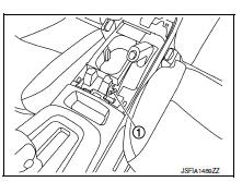
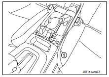
Engage parking brake lever, then lift up the end of the trim on the parking brake lever to access the adjusting nut.
-
Insert a suitable tool onto adjusting nut (1). Rotate adjusting nut to fully loosen cable, and then release parking brake lever.
-
Depress the foot brake about 10 times and adjust the rear shoe clearance.
CAUTION:
Be sure to securely depress the foot brake.
-
Rotate brake drum to make sure that there is no drag.
-
Adjust parking brake cable with the following procedure.
-
When replace parking brake cable, operate parking brake lever with a force of 400 N (40.8 kg-f, 89.9 lb-f) about 10 times.
-
Engage parking brake lever, then lift up the end of the trim on the parking brake lever to access the adjusting nut.
-
Rotate adjusting nut to adjust parking brake lever stroke using suitable tool.
-
Operate parking brake lever with a force of 196 N (20.0 kg-f, 44.1 lb-f), make sure the parking brake lever stroke is within the specified number of notches. (Check it by listening and counting ratchet clicks.)
Number of notches Refer to PB-13, "Parking Brake Control".
-
Make sure that there is no drag on rear brake with parking brake lever completely released.
-
Install center console cup holder finisher. Refer to IP-17, "Exploded View".
ADJUSTMENT - Disc Brakes
-
Remove rear wheels and tires using power tool. Refer to WT-47, "Adjustment".
-
Secure both disc rotors to wheel hubs using wheel nuts.
-
Remove the adjusting hole plug from the disc rotor. Turn the adjuster (1) in the direction (A) as shown using suitable tool until the disc rotor is locked.
-
Turn back the adjuster 7 notches from the locked position.
-
Rotate the disc rotor to check that there is no drag. Install the adjuster hole plug. Refer to PB-11, "Inspection and Adjustment"
-
Adjust the cable with the following procedure.
-
Operate the parking brake lever with a force of 400 N (40.8 kg-f, 89.9 lb-f) for 10 strokes or more.
-
Remove center console cup holder finisher. Refer to IP-17, "Exploded View".
-
Insert suitable tool onto adjusting nut (1). Adjust the parking brake lever stroke by turning the adjusting nut (1).
CAUTION:
Make sure to securely depress the brake pedal.
-
Operate the parking brake lever with a force of 196 N (20.0 kg-f, 44.1 lb-f). Check that the parking brake lever stroke is within the specified number of notches. (Check it by listening to the clicks of the ratchet.)
Number of notches : Refer to PB-13, "Parking Brake Control".
-
Rotate the disc rotor to check that there is no drag. Refer to PB-11, "Inspection and Adjustment".
-
Install center console cup holder finisher. Refer to IP-17, "Exploded View".
 Basic inspection
...
 Parking brake shoe
Adjustment - Drum Brake
If equipped with drum brakes, refer to PB-11, "Inspection and
Adjustment".
Adjustment - Disc Brake
Adjust parking brake lever stroke. Refer to PB-4,
&q ...
Other materials:
Moonroof switch
Removal and installation
REMOVAL
Remove the map lamp. Refer to INL-52, "Removal and Installation".
Release the pawls and remove the moonroof switch finisher (1).
: Pawl
Release the pawls and remove the moonroof switch (2).
: Pawl
INSTALLATION
Installation is in the ...
Symptom diagnosis
Noise, vibration and harshness (NVH) troubleshooting
NVH troubleshooting chart
Locate the area where noise occurs.
Confirm the type of noise.
Specify the operating condition of engine.
Check specified noise source.
If necessary, repair or replace these parts.
Closely relate ...
Precaution for Supplemental Restraint System (SRS) "AIR BAG"
and "SEAT BELT PRE-TENSIONER"
The Supplemental Restraint System such as “AIR BAG” and “SEAT
BELT PRE-TENSIONER”, used along
with a front seat belt, helps to reduce the risk or severity of injury to the
driver and front passenger for certain
types of collision. Information necessary to service the system ...
