Nissan Sentra B18 (2020-2025) Service Manual: P2a01 O2 Sensor 2 Bank 1
Dtc Description
The heated oxygen sensor 2 has a much longer switching time between rich and lean than the air fuel ratio (A/F) sensor 1. The oxygen storage capacity of the three way catalyst (manifold) causes the longer switching time.
MALFUNCTION A
To judge the malfunctions of heated oxygen sensor 2, ECM monitors whether the voltage is unusually high during various driving conditions such as fuel cut.
MALFUNCTION B
To judge the malfunctions of heated oxygen sensor 2, ECM monitors whether the minimum voltage is excessively high during various driving conditions such as fuel cut.
-
An excessively high voltage from the sensor is sent to ECM.
-
The minimum voltage from the sensor is not reached to the specified voltage.
|
DTC |
CONSULT screen terms (Trouble diagnosis content) |
DTC detection condition |
||
|
P2A01 |
O2 sensor bank 1 sensor 2 (O2 sensor circuit range/performance bank 1 sensor 2) |
A |
Diagnosis condition |
— |
|
Signal (terminal) |
Voltage signal transmitted from heated oxygen sensor 2 to ECM |
|||
|
Threshold |
An excessively high voltage from the sensor is sent to ECM |
|||
|
Diagnosis delay time |
— |
|||
|
B |
Diagnosis condition |
— |
||
|
Signal (terminal) |
Voltage signal transmitted from heated oxygen sensor 2 to ECM |
|||
|
Threshold |
The minimum voltage from the sensor is not reached to the specified voltage |
|||
|
Diagnosis delay time |
— |
|||
POSSIBLE CAUSE
P2A01-A
-
Harness or connectors (The heated oxygen sensor 2 circuit is open or shorted.)
-
Heated oxygen sensor 2
P2A01-B
-
Harness or connectors (The heated oxygen sensor 2 circuit is open or shorted.)
-
Heated oxygen sensor 2
-
Fuel pressure
-
Fuel injector
FAIL-SAFE
Not applicable
Confirmation Procedure
-
PRECONDITIONING
If DTC Confirmation Procedure has been previously conducted, always perform the following procedure before conducting the next test.
>>GO TO 2.
-
DTC CONFIRMATION PROCEDURE FOR MALFUNCTION A
-
Start engine and warm it up to the normal operating temperature.
-
Turn ignition switch OFF and wait at least 10 seconds.
-
Restart engine and keep the engine speed between 3,500 and 4,000 rpm for at least 1 minute under no load.
-
Check 1st trip DTC.
Is 1st trip DTC detected?
YES >>Proceed to DTC Diagnosis Procedure.
NO-1 >>With CONSULT: GO TO 3.
NO-2 >>Without CONSULT: GO TO 5.
-
-
DTC CONFIRMATION PROCEDURE FOR MALFUNCTION B-1
 WITH CONSULT
Test condition : For better results, perform “DTC WORK SUPPORT” at a temperature of 0 to 30°C (32 to 86°F).
-
Turn ignition switch ON and select “DATA MONITOR” mode with CONSULT.
-
Start engine and warm it up to the normal operating temperature.
-
Turn ignition switch OFF and wait at least 10 seconds.
-
Restart engine and keep the engine speed between 3,500 and 4,000 rpm for at least 1 minute under no load.
-
Let engine idle for 1 minute.
-
Check that “COOLAN TEMP/S” indicates more than 70°C (158°F).
If not, warm up engine and go to next step when “COOLAN TEMP/S” indication reaches 70°C (158°F).
-
Open engine hood.
-
Select “O2 (B1) P0138” of “HO2S2” in “DTC WORK SUPPORT” mode with CONSULT.
-
Follow the instruction of CONSULT display.
Note:
It will take at most 10 minutes until “COMPLETED”is displayed.
-
Touch “SELF-DIAG RESULTS”.
Which is displayed on CONSULT screen?
OK-1>>To check malfunction symptom before repair: Refer to Intermittent Incident.
OK-2>>Confirmation after repair: INSPECTION END
NG>>Proceed to DTC Diagnosis Procedure.
CAN NOT BE DIAGNOSED>>GO TO 4.
-
-
DTC CONFIRMATION PROCEDURE FOR MALFUNCTION B-2
-
Turn ignition switch OFF and leave the Nissan Sentra vehicle in a cool place (soak the vehicle).
-
Perform DTC confirmation procedure again.
GO TO 3.
-
-
PERFORM COMPONENT FUNCTION CHECK-1
Note: WITHOUT CONSULT
Use component function check to check the overall function of the heated oxygen sensor 2 circuit. During this check, a 1st trip DTC might not be confirmed.
-
Start engine and warm it up to the normal operating temperature.
-
Turn ignition switch OFF and wait at least 10 seconds.
-
Restart engine and keep the engine speed between 3,500 and 4,000 rpm for at least 1 minute under no load.
-
Let engine idle for 1 minute.
-
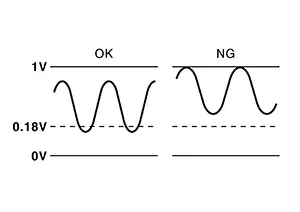
Check the voltage between ECM harness connector terminals under the following conditions.
ECM
Condition
Voltage
Connector
+
–
Terminal
F25
77
76
Revving up to 4,000 rpm quickly under no load at least 10 times. (Depress and release the accelerator pedal as quickly as possible.)
The voltage should be above 0.73 V at least once during this procedure.
The voltage should be below 0.18 V at least once during this procedure.
Is the inspection result normal?
YES-1 >>To check malfunction symptom before repair: Refer to Intermittent Incident.
YES-2 >>Confirmation after repair: INSPECTION END
NO >>GO TO 6.
-
-
PERFORM COMPONENT FUNCTION CHECK-2
WITHOUT CONSULTCheck the voltage between ECM harness connector terminals under the following conditions.
ECM
Condition
Voltage
Connector
+
–
Terminal
F25
77
76
Keeping engine at idle for 10 minutes.
The voltage should be above 0.73 V at least once during this procedure.
The voltage should be below 0.18 V at least once during this procedure.
Is the inspection result normal?
YES-1 >>To check malfunction symptom before repair: Refer to Intermittent Incident.
YES-2 >>Confirmation after repair: INSPECTION END
NO >>GO TO 7.
-
PERFORM COMPONENT FUNCTION CHECK-3
Check the voltage between ECM harness connector terminals under the following conditions.
CAUTION:
Always drive Nissan Sentra vehicle at a safe speed.
ECM
Condition
Voltage
Connector
+
–
Terminal
F25
77
76
Coasting from 80 km/h (50 MPH) with selector lever in the D position.
The voltage should be above 0.73 V at least once during this procedure.
The voltage should be below 0.18 V at least once during this procedure.
Is the inspection result normal?
YES-1 >>To check malfunction symptom before repair: Refer to Intermittent Incident.
YES-2 >>Confirmation after repair: INSPECTION END
NO >>Proceed to DTC Diagnosis Procedure.
Dtc Diagnosis Procedure
-
INSPECTION START
-
Confirm the detected malfunction (A or B). Refer to DTC Description.
Which malfunction is detected?
A>>GO TO 2.
B>>GO TO 7.
-
-
CHECK HEATED OXYGEN SENSOR 2 CONNECTOR
-
Disconnect heated oxygen sensor 2 (HO2S2) harness connector.
-
Check that water is not inside connectors.
There is no leakage.
Is the inspection result normal?
YES >>GO TO 3.
NO >>Repair or replace malfunctioning part.
-
-
CHECK HO2S2 GROUND CIRCUIT FOR OPEN AND SHORT
-
Turn ignition switch OFF.
-
Disconnect ECM harness connector.
-
Disconnect heated oxygen sensor 2 (HO2S2) harness connector.
-
Check the continuity between HO2S2 harness connector and ECM harness connector.
HO2S2
ECM
Continuity
Connector
Terminal
Connector
Terminal
E72
1
F25
76
Existed
-
Also check harness for short to ground and short to power.
Is the inspection result normal?
YES >>GO TO 4.
NO >>Repair or replace malfunctioning part.
-
-
CHECK HO2S2 INPUT SIGNAL CIRCUIT FOR OPEN AND SHORT
-
Check the continuity between HO2S2 harness connector and ECM harness connector.
HO2S2
ECM
Continuity
Connector
Terminal
Connector
Terminal
E72
2
F25
77
Existed
-
Check the continuity between HO2S2 harness connector and ground, or ECM harness connector and ground.
HO2S2
Ground
Continuity
Connector
Terminal
E72
2
Ground
Not existed
ECM
Ground
Continuity
Connector
Terminal
F25
77
Ground
Not existed
-
Also check harness for short to ground and short to power.
Is the inspection result normal?
YES >>GO TO 5.
NO >>Repair or replace malfunctioning part.
-
-
CHECK HEATED OXYGEN SENSOR 2
Refer to Component Inspection.
Is the inspection result normal?
YES >>INSPECTION END
NO >>GO TO 6.
-
REPLACE HEATED OXYGEN SENSOR 2
Replace malfunctioning heated oxygen sensor 2. Refer to Exploded View.
CAUTION:
-
Discard any heated oxygen sensor which has been dropped from a height of more than 0.5 m (19.7 in) onto a hard surface such as a concrete floor; use a new one.
-
Before installing new oxygen sensor, clean exhaust system threads.
INSPECTION END
-
-
CLEAR THE MIXTURE RATIO SELF-LEARNING VALUE
-
Start engine and warm it up to the normal operating temperature.
-
Clear the mixture ratio self-learning value. Refer to Work Procedure.
-
Run engine for at least 10 minutes at idle speed.
Is the 1st trip DTC P0172 detected? Is it difficult to start engine?
YES >>Perform trouble diagnosis for DTC P0172. Refer to DTC Diagnosis Procedure.
NO >>GO TO 8.
-
-
CHECK HEATED OXYGEN SENSOR 2 GROUND CIRCUIT FOR OPEN AND SHORT
-
Turn ignition switch OFF.
-
Disconnect ECM harness connector.
-
Disconnect heated oxygen sensor 2 (HO2S2) harness connector.
-
Check the continuity between HO2S2 harness connector and ECM harness connector.
HO2S2
ECM
Continuity
Connector
Terminal
Connector
Terminal
E72
1
F25
76
Existed
-
Also check harness for short to ground and short to power.
Is the inspection result normal?
YES >>GO TO 9.
NO >>Repair or replace malfunctioning part.
-
-
CHECK HO2S2 INPUT SIGNAL CIRCUIT FOR OPEN AND SHORT
-
Check the continuity between HO2S2 harness connector and ECM harness connector.
HO2S2
ECM
Continuity
Connector
Terminal
Connector
Terminal
E72
2
F25
77
Existed
-
Check the continuity between HO2S2 harness connector and ground, or ECM harness connector and ground.
HO2S2
Ground
Continuity
Connector
Terminal
E72
2
Ground
Not existed
ECM
Ground
Continuity
Connector
Terminal
F25
77
Ground
Not existed
-
Also check harness for short to ground and short to power.
Is the inspection result normal?
YES >>GO TO 10.
NO >>Repair or replace malfunctioning part.
-
-
CHECK HEATED OXYGEN SENSOR 2
Refer to Component Inspection.
Is the inspection result normal?
YES >>INSPECTION END
NO >>GO TO 11.
-
REPLACE HEATED OXYGEN SENSOR 2
Replace malfunctioning heated oxygen sensor 2. Refer to Exploded View.
CAUTION:
-
Discard any heated oxygen sensor which has been dropped from a height of more than 0.5 m (19.7 in) onto a hard surface such as a concrete floor; use a new one.
-
Before installing new oxygen sensor, clean exhaust system threads.
INSPECTION END
-
 P2619 Crankshaft Position Sensor
Dtc Description
DTC Description
DTC DETECTION LOGIC
DTC
CONSULT screen terms
(Trouble ...
 P2b95 Cold Start Control
Dtc Description
DTC Description
ECM controls fuel injection timing and fuel injection quantity
when engine is started with the engine cold.
This control promotes the activation of three way ...
Other materials:
Ball Joint
Ball Joint
Swing torque
0.5 – 4.9 N·m (0.05
– 0.50 kg-m, 4 – 43 in-lb)
Measurement on spring
balance
15.4 – 150 ...
Removal and installation
Starter motor
Exploded View
“S” terminal harness
“B” terminal harness
Starter motor
Cylinder block
Removal and Installation
NOTE:
When removing components such as hoses, tubes/lines, etc., cap or plug
openings to prevent fluid from spilling.
REMOVAL
Dis ...
The Door Open Warning Continues Displaying, or Does Not Display
Description
Description
The door ajar warning is displayed even though
all of the doors are closed.
The door ajar warning is not displayed even
though a door is ajar.
Diagnosis Procedure
Diagnosis Procedure
CHECK BCM INPUT S ...
