Nissan Sentra Service Manual: P0746 Pressure control solenoid A
DTC Logic
DTC DETECTION LOGIC
| DTC | CONSULT screen terms (Trouble diagnosis content) | DTC detection condition | Possible causes |
| P0746 | PRESSURE CONTROL SOLENOID A (Pressure Control Solenoid A Performance/Stuck Off) | The detecting condition A or detection condition
B is detected twice or more (1 second or
more later after detection of the first) in the
same DC under the following diagnosis conditions: Diagnosis conditions
Detection condition A
Detection condition B
|
|
NOTE:
DC stands for “DRIVING CYCLE” and indicates a series of driving cycle of “Ignition switch OFF → ON → driving → OFF”.
DTC CONFIRMATION PROCEDURE
CAUTION:
Be careful of the driving speed.
1.PREPARATION BEFORE WORK
If another “DTC CONFIRMATION PROCEDURE” occurs just before, turn ignition switch OFF and wait for at least 10 seconds, then perform the next test.
>> GO TO 2.
2.CHECK DTC DETECTION
- Start the engine.
- Drive the vehicle.
- Maintain the following conditions for 10 seconds or more.
Selector lever : “D” position
Accelerator pedal position : 0.1/8 or more
Vehicle speed : 40 km/h (25 MPH) or more
- Stop the vehicle.
- Check the first trip DTC.
Is “P0746”detected? YES >> Go to TM-191, "Diagnosis Procedure".
NO >> INSPECTION END
Diagnosis Procedure
1.CHECK LINE PRESSURE SOLENOID VALVE
- Turn ignition switch OFF.
- Disconnect CVT unit connector.
- Check line pressure solenoid valve. Refer to TM-191, "Component Inspection"
Is the inspection result normal? YES >> GO TO 2.
NO >> Repair or replace malfunctioning parts.
2.CHECK LINE PRESSURE
Perform line pressure test. Refer to TM-149, "Work Procedure".
Is the inspection result normal? YES >> Check intermittent incident. Refer to GI-39, "Intermittent Incident".
NO >> Repair or replace the malfunction items.
Component Inspection
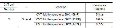
1.CHECK LINE PRESSURE SOLENOID VALVE
Check resistance between CVT unit connector terminal and ground.
 Is the inspection
result normal?
YES >> INSPECTION END
NO >> There is a malfunction of line pressure solenoid valve. Replace transaxle assembly. Refer to TM- 283, "Removal and Installation".
 P0744 Torque converter
DTC Logic
DTC DETECTION LOGIC
DTC
CONSULT screen terms
(Trouble diagnosis content)
DTC detection condition
Possible causes
P0744
TORQUE CONVERTER
(Torque converter ...
 P0846 Transmission fluid pressure SEN/SW B
DTC Logic
DTC DETECTION LOGIC
DTC
CONSULT screen terms
(Trouble diagnosis content)
DTC detection condition
Possible causes
P0846
TRANSMISSION FLUID
PRESSURE SEN/SW ...
Other materials:
C1115 ABS Sensor [abnormal signal]
DTC Logic
DTC DETECTION LOGIC
DTC
Display Item
Malfunction detected condition
Possible causes
C1115
ABS SENSOR
[ABNORMAL SIGNAL]
When difference in wheel speed between any wheel
and others is detected while the vehicle is driven, because
of installation of t ...
Break-in schedule
CAUTION
During the first 1,200 miles (2,000 km),
follow these recommendations to obtain
maximum engine performance and ensure
the future reliability and economy of your
new vehicle. Failure to follow these recommendations
may result in shortened
engine life and reduced engine
performance.
A ...
Wiring diagram
Door mirror
Wiring diagram
Inside mirror
Wiring Diagram
...
