Nissan Sentra Service Manual: P0706 Transmission range sensor A
DTC Logic
DTC DETECTION LOGIC
| DTC | CONSULT screen terms (Trouble diagnosis content) | DTC detection condition | Possible causes |
| P0706 | T/M RANGE SENSOR A (Transmission Range Sensor A Circuit Range/Performance) | All range signals stay OFF continuously for 30
seconds under the following diagnosis condition
1 and 2:
|
|
DTC CONFIRMATION PROCEDURE
1.PREPARATION BEFORE WORK
If another “DTC CONFIRMATION PROCEDURE” occurs just before, turn ignition switch OFF and wait for at least 10 seconds, then perform the next test.
>> GO TO 2.
2.PERFORM DTC CONFIRMATION PROCED
- Start the engine.
- Maintain the following conditions
Accelerator pedal position : 0.0/8
Brake pedal : Depressed
Vehicle speed : 0 km/h (0 MPH)
- Shift the selector lever through entire positions from “P” to “L”. (Hold the selector lever at each position for 35 seconds or more.)
- Check the first trip DTC.
Is “P0706” detected? YES >> Go to TM-167, "Diagnosis Procedure".
NO >> INSPECTION END
Diagnosis Procedure
1.ADJUSTMENT OF CONTROL CABLE
Adjust control cable. Refer to TM-150, "Adjustment".
>> GO TO 2.
2.PERFORM DTC CONFIRMATION PROCEDURE
 With CONSULT
- Turn ignition switch ON.
- Select “Self Diagnostic Results” in “TRANSMISSION”.
- Touch “Erase”.
- Perform “DTC CONFIRMATION PROCEDURE”. Refer to TM-167, "DTC Logic".
Is “P0706” detected? YES >> GO TO 3.
NO >> INSPECTION END
3.CHECK POWER CIRCUIT
- Turn ignition switch OFF.
- Disconnect transmission range switch connector.
- Turn ignition switch ON.
- Check voltage between transmission range switch harness connector terminal and ground.
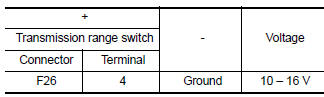
Is the check result normal? YES >> GO TO 4.
NO >> GO TO 7.
4.CHECK CIRCUIT BETWEEN TRANSMISSION RANGE SWITCH AND TCM (PART 1)
- Turn ignition switch OFF.
- Disconnect TCM connector.
- Check continuity between transmission range switch harness connector terminals and TCM harness connector terminals.
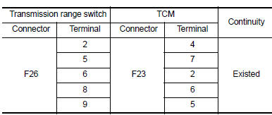
Is the check result normal? YES >> GO TO 5.
NO >> Repair or replace malfunctioning parts.
5.CHECK CIRCUIT BETWEEN TRANSMISSION RANGE SWITCH AND TCM (PART 2)
Check continuity between transmission range switch harness connector terminals and ground.
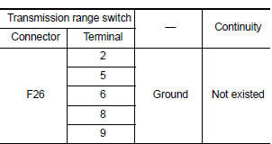
Is the check result normal? YES >> GO TO 6.
NO >> Repair or replace malfunctioning parts.
6.CHECK TRANSMISSION RANGE SWITCH
Check transmission range switch. Refer to TM-169, "Component Inspection".
Is the check result normal? YES >> Check intermittent incident. Refer to GI-39, "Intermittent Incident".
NO >> Repair or replace malfunctioning parts.
7.DETECT MALFUNCTIONING ITEMS
Check the following items:
- Harness open circuit or short circuit between ignition switch and IPDM E/R. Refer to PG-20, "Wiring Diagram — Ignition Power Supply —".
- Harness open circuit or short circuit between IPDM E/R and transmission range switch.
- 10A fuse (No. 45, IPDM E/R). Refer to PG-49, "IPDM E/R Terminal Arrangement".
- IPDM E/R
Is the check result normal? YES >> Check intermittent incident. Refer to GI-39, "Intermittent Incident".
NO >> Repair or replace malfunctioning parts.
Component Inspection
1.CHECK TRANSMISSION RANGE SWITCH
Check continuity between transmission range switch connector terminals.
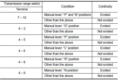
Is the inspection result normal? YES >> INSPECTION END
NO >> There is a malfunction of transmission range switch. Replace transaxle assembly. Refer to TM- 283, "Removal and Installation".
 P0705 Transmission range sensor A
DTC Logic
DTC DETECTION LOGIC
DTC
CONSULT screen terms
[Trouble diagnosis content]
DTC detection condition
Possible causes
P0705
T/M RANGE SENSOR A
[Transmission R ...
 P0711 Transmission fluid temperature sensor A
DTC Logic
DTC DETECTION LOGIC
DTC
CONSULT screen terms
(Trouble diagnosis content)
DTC detection condition
Possible causes
P0711
FLUID TEMP SENSOR A
(Transmission F ...
Other materials:
L terminal circuit (short)
Description
The terminal “l” circuit controls the charge warning lamp. The charge warning
lamp turns on when the ignition
switch is set to on or start. When the generator is providing sufficient voltage
with the engine running,
the charge warning lamp turns off. If the charge warni ...
Periodic maintenance
M/T OIL
Inspection
OIL LEAKAGE
Make sure that gear oil is not leaking from transaxle or around it.
OIL LEVEL
Remove filler plug (1) and gasket from transaxle case.
Check the oil level from filler plug mounting hole as shown.
CAUTION:
Do not start engine while checking oil level.
Se ...
Ecu diagnosis information
ECM
Reference Value
VALUES ON THE DIAGNOSIS TOOL
NOTE:
The following table includes information (items) inapplicable to this
vehicle. For information (items) applicable
to this vehicle, refer to CONSULT display items.
Numerical values in the following table are reference values.
Thes ...
