Nissan Sentra B18 (2020-2025) Service Manual: P052b Intake Valve Timing Control
Dtc Description
DTC DETECTION LOGIC
|
DTC No. |
CONSULT screen terms (Trouble diagnosis content) |
DTC detecting condition |
|---|---|---|
|
P052B |
CAMSHAFT POSITION TIMING B1 (Cold start ŌĆ£AŌĆØ camshaft position timing over-retarded bank 1) |
There is a gap between angle of target and phase-control angle degree when the engine is in a cold condition. |
POSSIBLE CAUSE
-
Crankshaft position sensor
-
Intake camshaft position sensor
-
Intake valve timing control actuator
-
Accumulation of debris to the signal pick-up portion of the camshaft
-
Timing chain installation
-
Foreign matter caught in the oil groove for intake valve timing control
FAIL-SAFE
Engine Control System
|
Engine operating condition in fail-safe mode |
||
|---|---|---|
|
Fail safe mode |
Nissan Sentra Vehicle behavior |
|
|
Device fix mode |
|
|
|
Others |
ECM stops the electric valve timing control. (The camshaft returns to the position of most retard angle.) |
|
Idle Start/Stop System
When a DTC is detected, the start/stop indicator lamp blinks slowly and the idle start/stop system operation is prohibited.
When ECM detects error while operating the idle start/stop system, ECM restarts the engine.
Confirmation Procedure
-
PRECONDITIONING
TESTING CONDITION:
Before performing the following procedure, confirm that battery voltage is 10 V or more at idle.
 With CONSULT
-
Turn ignition switch OFF and wait at least 10 seconds.
-
Turn ignition switch ON.
-
Turn ignition switch OFF and wait at least 10 seconds.
-
Turn ignition switch ON.
-
On the CONSULT screen, select ŌĆ£ENGINEŌĆØ >> ŌĆ£DATA MONITORŌĆØ >> ŌĆ£COOLAN TEMP/SŌĆØ.
-
Check ŌĆ£COOLAN TEMP/SŌĆØ indication value.
 With GST
Follow the procedure ŌĆ£With CONSULTŌĆØ above.
Is the value of ŌĆ£COOLAN TEMP/SŌĆØŌłÆ5┬░C (23┬░F) and 45┬░C (113┬░F)?
YES >>GO TO 2.
NO-1 [if it is below ŌłÆ5┬░C (23┬░F)] >>Warm up the engine until the value of ŌĆ£COOLAN TEMP/SŌĆØ indicates ŌłÆ5┬░C (23┬░F) and 45┬░C (113┬░F). And then GO TO 2.
NO-2 [if it is above 45┬░C (113┬░F)] >>Cool the engine down to the value of ŌĆ£COOLAN TEMP/SŌĆØ indicates ŌłÆ5┬░C (23┬░F) and 45┬░C (113┬░F). And then GO TO 2.
-
-
PERFORM DTC CONFIRMATION PROCEDURE
-
Turn ignition switch OFF and wait at 10 seconds.
-
Turn ignition switch ON.
-
Set the selector lever in N range.
-
Start the engine and let it idle for 20 seconds or more.
-
Check 1st trip DTC.
Is 1st trip DTC detected?
YES >>Refer to DTC Diagnosis Procedure.
NO >>INSPECTION END
-
Dtc Diagnosis Procedure
-
INSPECTION START
With CONSULT>>GO TO 2.
Without CONSULT>>GO TO 3.
-
CHECK VTC POSITION
With CONSULT-
Turn ignition switch ON.
-
On the CONSULT screen, select ŌĆ£ENGINEŌĆØ >> ŌĆ£DATA MONITORŌĆØ >> ŌĆ£COOLAN TEMP/SŌĆØ.
-
Check that the ŌĆ£COOLAN TEMP/SŌĆØ indication value is between ŌłÆ5┬░C (23┬░F) and 45┬░C (113┬░F).
-
Start engine and wait at least 5 seconds.
-
On the CONSULT screen, select ŌĆ£ENGINEŌĆØ >> ŌĆ£DATA MONITORŌĆØ >> ŌĆ£INT/V TIM (B1)ŌĆØ.
-
Check that the data monitor item indicates as follows:
Item
Value (┬░CA)
INT/V TIM (B1)
10 ┬▒ 2
Is the inspection result normal?
YES >>GO TO 10.
NO >>GO TO 3.
-
-
CHECK OIL PRESSURE WARNING LAMP
-
Start engine.
-
Check that oil pressure warning lamp is not illuminated.

Is oil pressure warning lamp illuminated?
YES >>Refer to Inspection.
NO >>GO TO 4.
-
-
CHECK INTAKE VALVE TIMING CONTROL ACTUATOR
Perform Component Inspection of the intake valve timing intermediate lock control actuator. Refer to DTC Diagnosis Procedure.
Is the inspection result normal?
YES >>GO TO 5.
NO >>Repair or replace error-detected parts.
-
CHECK CRANKSHAFT POSITION SENSOR
Perform Component Inspection of the crankshaft position sensor. Refer to Component Inspection.
Is the inspection result normal?
YES >>GO TO 6.
NO >>Repair or replace error-detected parts.
-
CHECK INTAKE CAMSHAFT POSITION SENSOR
Perform Component Inspection of the intake camshaft position sensor. Refer to Component Inspection.
Is the inspection result normal?
YES >>GO TO 7.
NO >>Repair or replace error-detected parts.
-
CHECK CAMSHAFT (INTAKE)
Check the following.
-
Accumulation of debris on the signal plate of camshaft
 front end
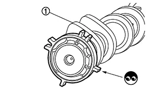
-
Chipping signal plate of camshaft front end
Is the inspection result normal?
YES >>GO TO 8.
NO >>Remove debris and clean the signal plate of camshaft front end or replace camshaft. Refer to Removal and Installation.
-
-
CHECK TIMING CHAIN INSTALLATION
Check service records for any recent repairs that may cause timing chain misalignment.
Are there any service records that may cause timing chain misalignment?
YES >>Check timing chain installation. Refer to Removal and Installation.
NO >>GO TO 9.
-
CHECK LUBRICATION CIRCUIT
Perform ŌĆ£Inspection of Camshaft Sprocket (INT) Oil GrooveŌĆØ. Refer to Inspection.
Is the inspection result normal?
YES >>GO TO 10.
NO >>Clean lubrication line.
-
CHECK INTERMITTENT INCIDENT
Refer to Intermittent Incident.
>>INSPECTION END
 P052a Intake Valve Timing Control
Dtc Description
DTC Description
DTC DETECTION LOGIC
DTC No.
CONSULT screen terms
(Trouble di ...
 P0531 A/c Refrigerant Pressure Sensor
Dtc Description
DTC Description
DTC DETECTION LOGIC
DTC No.
Trouble diagnosis
name
...
Other materials:
Precaution for Supplemental Restraint System (srs) "air Bag" and "seat Belt Pre-Tensioner"
Precaution for Supplemental Restraint System (SRS) "AIR BAG" and "SEAT BELT PRE-TENSIONER"
The Supplemental Restraint System such as
ŌĆ£AIR BAGŌĆØ and ŌĆ£SEAT BELT PRE-TENSIONERŌĆØ,
used along with a front seat belt, helps to reduce the risk or
severity of injury to the driver and fron ...
Dtc Description
DTC Description
DTC DETECTION LOGIC
DTC No.
CONSULT screen terms
(Trouble diagnosis content)
DTC detection condition
...
Removal and installation
Ipdm e/r
Exploded view
Ipdm e/r
IPDM E/R cover A
Ipdm e/r cover b
Removal and installation
Caution:
Ipdm e/r integrated relays are not serviceable and must not be removed
from unit.
Removal
Remove inlet air duct (upper). Refer to em-25, "removal and
installation" ...
