Nissan Sentra Service Manual: P0520 EOP System
DTC Logic
DTC DETECTION LOGIC
| DTC No. | CONSULT screen terms (Trouble diagnosis content) | DTC detecting condition | Possible cause |
| P0520 | EOP SENSOR/SWITCH (Engine oil pressure sensor/ switch circuit) | ECM detects the following status continuously
for 5 seconds or more:
|
|
DTC CONFIRMATION PROCEDURE
1.PRECONDITIONING
If DTC Confirmation Procedure has been previously conducted, always perform the following procedure before conducting the next test.
- Turn ignition switch OFF and wait at least 10 seconds.
- Turn ignition switch ON.
- Turn ignition switch OFF and wait at least 10 seconds.
>> GO TO 2.
2.CHECK ENGINE OIL LEVEL
- Turn ignition switch OFF.
- Check engine oil level. Refer to LU-7, "Inspection".
Is inspection result normal? YES >> GO TO 3.
NO >> Check engine oil leak. Refer to LU-6, "Engine Lubrication System Schematic".
3.PERFORM DTC CONFIRMATION PROCEDURE
- Start engine and let it idle for at least 5 seconds.
- Check 1st trip DTC.
Is 1st trip DTC detected? YES >> Proceed to EC-340, "Diagnosis Procedure".
NO >> INSPECTION END
Diagnosis Procedure
1.CHECK EOP SENSOR POWER SUPPLY CIRCUIT-1
- Turn ignition switch OFF.
- Disconnect EOP sensor harness connector.
- Turn ignition switch ON.
- Check the voltage between EOP sensor harness connector terminals.
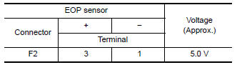
Is the inspection result normal? YES >> GO TO 2.
NO >> GO TO 4.
2.CHECK EOP SENSOR SIGNAL CIRCUIT
- Turn ignition switch OFF
- Disconnect ECM harness connectors.
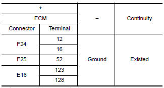
- Check the continuity between EOP sensor harness connector and ECM harness connector.
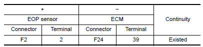
- Also check harness for short to ground and short to power.
Is the inspection result normal? YES >> GO TO 3.
NO >> Repair or replace error-detected parts.
3.CHECK EOP SENSOR
Check EOP sensor. Refer to EC-342, "Component Inspection (EOP Sensor)".
Is the inspection result normal? YES >> Check intermittent incident. Refer to GI-39, "Intermittent Incident".
NO >> Replace EOP sensor. Refer to EM-94, "Exploded View".
4.CHECK EOP SENSOR POWER SUPPLY CIRCUIT-2
Check the voltage between EOP sensor harness connector terminal and ground.
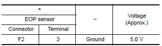
Is the inspection result normal? YES >> GO TO 6.
NO >> GO TO 5.
5.CHECK SENSOR POWER SUPPLY 2 CIRCUIT
Check sensor power supply 2 circuit. Refer to EC-444, "Diagnosis Procedure".
Is inspection result normal? YES >> Perform the trouble diagnosis for power supply circuit.
NO >> Repair or replace error-detected parts.
6.CHECK EOP SENSOR GROUND CIRCUIT
- Turn ignition switch OFF.
- Disconnect ECM harness connector.
- Check the continuity between EOP sensor harness connector and ECM harness connector.
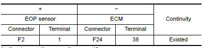
Is the inspection result normal? YES >> GO TO 7.
NO >> Repair or replace error-detected parts.
7.CHECK ECM GROUND CIRCUIT
Check the continuity between ECM harness connector and ground.
Is the inspection result normal? YES >> Check intermittent incident. Refer to GI-39, "Intermittent Incident".
NO >> Repair or replace error-detected parts.
Component Inspection (EOP Sensor)
1.CHECK EOP SENSOR
- Turn ignition switch OFF.
- Disconnect EOP sensor harness connector.
- Check the resistance between EOP sensor connector terminals.
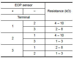
Is the inspection result normal? YES >> INSPECTION END
NO >> Replace EOP sensor. Refer to EM-94, "Exploded View".
 P050A, P050B, P050E Cold start control
Description
ECM controls ignition timing and engine idle speed when engine is started
with pre-warming up condition.
This control promotes the activation of three way catalyst by heating the
c ...
 P0524 Engine oil pressure
DTC Logic
DTC DETECTION LOGIC
DTC No.
CONSULT screen terms
(Trouble diagnosis content)
DTC detecting condition
Possible cause
P0524
ENGINE OIL PRESSURE
(Engine oil ...
Other materials:
Plug
Description
Replace the O-ring if oil leakage or exudes from the plug.
Exploded View
Plug
O-ring
O-ring
Plug
: Always replace after every
disassembly.
: NВ·m (kg-m, ft-lb)
: NВ·m (kg-m, in-lb)
: Genuine NISSAN CVT Fluid NS-3
Removal and Installation
NOTE:
Replace ...
Rear lh side power window does not operate
When both power window main switch and rear power window switch lh are
operated
When both power window main switch and rear power window switch lh are
operated : diagnosis procedure
1.CHECK REAR POWER WINDOW SWITCH LH
Check rear power window switch LH.
Refer to PWC-40, "REAR POWER WIN ...
Power window main switch
Reference Value
TERMINAL LAYOUT
PHYSICAL VALUES
MAIN POWER WINDOW AND DOOR LOCK/UNLOCK SWITCH
Fail Safe
FAIL-SAFE CONTROL
Switches to fail-safe control when malfunction is detected in encoder signal
that detects up/down speed and
direction of door glass. Switches to fail-safe co ...
