Nissan Sentra B18 (2020-2025) Service Manual: P0441 Evap Control System
Dtc Description
DTC Description
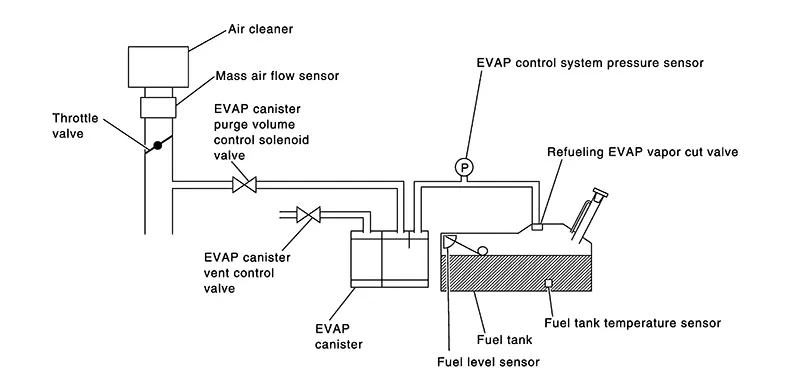
In this evaporative emission (EVAP) control system, purge flow occurs during non-closed throttle conditions. Purge volume is related to air intake volume. Under normal purge conditions (non-closed throttle), the EVAP canister purge volume control solenoid valve is open to admit purge flow. Purge flow exposes the EVAP control system pressure sensor to intake manifold vacuum.
Under normal conditions (non-closed throttle), sensor output voltage indicates if pressure drop and purge flow are adequate. If not, a malfunction is determined.
DTC DETECTION LOGIC
|
DTC |
CONSULT screen terms (Trouble diagnosis content) |
DTC detection condition |
|
|
P0441 |
EVAP PURG FLOW/MON (Evaporative emission system incorrect purge flow) |
Diagnosis condition |
ŌĆö |
|
Signal (terminal) |
ŌĆö |
||
|
Threshold |
EVAP control system does not operate properly, EVAP control system has a leak between intake manifold and EVAP control system pressure sensor |
||
|
Diagnosis delay time |
ŌĆö |
||
POSSIBLE CAUSE
-
EVAP canister purge volume control solenoid valve stuck closed
-
EVAP control system pressure sensor and the circuit
-
Loose, disconnected or improper connection of rubber tube
-
Blocked rubber tube
-
Cracked EVAP canister
-
EVAP canister purge volume control solenoid valve circuit
-
Accelerator pedal position sensor
-
Blocked purge port
-
EVAP canister vent control valve
FAIL-SAFE
Not applicable
Confirmation Procedure
Confirmation Procedure
-
PRECONDITIONING
If DTC Confirmation Procedure has been previously conducted, always turn ignition switch OFF and wait at least 10 seconds before conducting the next test.
Will CONSULT be used?
YES >>GO TO 2.
NO >>GO TO 5.
-
PERFORM DTC CONFIRMATION PROCEDURE-1
 With CONSULT
TESTING CONDITION:
Always perform test at a temperature of 5┬░C (41┬░F) or more.
-
Start the engine and warm it up to normal operating temperature.
-
Turn ignition switch OFF and wait at least 10 seconds.
-
Turn ignition switch ON.
-
Turn ignition switch OFF and wait at least 10 seconds.
-
Start engine and let it idle for at least 70 seconds.
-
Select ŌĆ£PURG FLOW P0441ŌĆØ of ŌĆ£EVAPORATIVE SYSTEMŌĆØ in ŌĆ£DTC WORK SUPPORTŌĆØ mode of ŌĆ£ENGINEŌĆØ using CONSULT.
-
Touch ŌĆ£STARTŌĆØ.
Is ŌĆ£COMPLETEDŌĆØ displayed on CONSULT screen?
YES >>GO TO 4.
NO >>GO TO 3.
-
-
PERFORM DTC CONFIRMATION PROCEDURE-2
When the following conditions are met, ŌĆ£TESTINGŌĆØ will be displayed on the CONSULT screen. Maintain the conditions continuously until ŌĆ£TESTINGŌĆØ changes to ŌĆ£COMPLETEDŌĆØ. (It will take at least 35 seconds.)
Selector lever
Suitable position
VHCL SPEED SE
32 ŌĆō 120 km/h (20 ŌĆō 75 MPH)
ENG SPEED
500 ŌĆō 3,300 rpm
B/FUEL SCHDL
1.0 ŌĆō 6.5 msec
COOLANT TEMP/S
More than 0┬░C (32┬░F)
CAUTION:
Always drive Nissan Sentra vehicle at a safe speed.
Note:
If ŌĆ£TESTINGŌĆØ does not change for a long time, retry from step 2.
Is ŌĆ£COMPLETEDŌĆØ displayed on CONSULT screen?
YES >>GO TO 4.
NO >>Perform DTC CONFIRMATION PROCEDURE again. GO TO 2.
-
PERFORM DTC CONFIRMATION PROCEDURE-3
Touch ŌĆ£SELF-DIAG RESULTSŌĆØ.
Is ŌĆ£OKŌĆØ displayed on CONSULT screen?
YES-1 >>To check malfunction symptom before repair: Refer to Intermittent Incident.
YES-2 >>Confirmation after repair: INSPECTION END
NO >>Proceed to DTC Diagnosis Procedure.
-
PERFORM COMPONENT FUNCTION CHECK
Note:
Use component function check to check the overall monitoring function of the EVAP control system purge flow monitoring. During this check, a 1st trip DTC might not be confirmed.
 With GST
-
Lift up drive wheels.
-
Start engine (VDC switch OFF) and warm it up to normal operating temperature.
-
Turn ignition switch OFF and wait at least 10 seconds.
-
Start engine and wait at least 70 seconds.
-
Set voltmeter probes to ECM harness connector terminals as per the following.
ECM
Connector
+
ŌłÆ
Terminal
E16
131
158
-
Check EVAP control system pressure sensor value at idle speed and note it.
-
Establish and maintain the following conditions for at least 1 minute.
Air conditioner switch
ON
Headlamp switch
ON
Rear window defogger switch
ON
Engine speed
Approx. 3,000 rpm
Selector lever position
Any position other than P, N or R
-
Verify that EVAP control system pressure sensor value stays 0.1 V less than the value at idle speed (measured at step 6) for at least 1 second.
Is the inspection result normal?
YES-1 >>To check malfunction symptom before repair: Refer to Intermittent Incident.
YES-2 >>Confirmation after repair: INSPECTION END
NO >>Proceed to DTC Diagnosis Procedure.
-
Dtc Diagnosis Procedure
DTC Diagnosis Procedure
-
CHECK EVAP CANISTER
-
Turn ignition switch OFF.
-
Check EVAP canister for cracks.
Is the inspection result normal?
YES-1 >>With CONSULT: GO TO 2.
YES-2 >>Without CONSULT: GO TO 3.
NO >>Replace EVAP canister. Refer to Removal and Installation.
-
-
CHECK PURGE FLOW
With CONSULT-
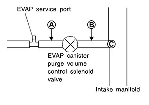
Disconnect vacuum hose connected to EVAP canister purge volume control solenoid valve at EVAP service port. Refer to Exploded View.
-
Start the engine and let it idle.
-
Select ŌĆ£PURG VOL CONT/VŌĆØ in ŌĆ£ACTIVE TESTŌĆØ mode of ŌĆ£ENGINEŌĆØ using CONSULT.
-
Touch ŌĆ£QdŌĆØ and ŌĆ£QuŌĆØ on CONSULT screen to adjust ŌĆ£PURG VOL CONT/VŌĆØ opening and check vacuum existence.
PURG VOL CONT/V
Vacuum
100%
Existed
0%
Not existed
Is the inspection result normal?
YES >>GO TO 7.
NO >>GO TO 4.
-
-
CHECK PURGE FLOW
 Without CONSULT
-
Start the engine and warm it up to normal operating temperature.
-
Stop the engine.
-
Disconnect vacuum hose connected to EVAP canister purge volume control solenoid valve at EVAP service port and install vacuum gauge. Refer to Exploded View.
-
Start engine and let it idle.
Never depress accelerator pedal even slightly.
-
Check vacuum gauge indication before 60 seconds pass after starting engine.
Vacuum should not exist.
-
Rev engine up to 2,000 rpm after 100 seconds pass after starting engine.
Vacuum should exist.
Is the inspection result normal?
YES >>GO TO 7.
NO >>GO TO 4.
-
-
CHECK EVAP PURGE LINE
-
Turn ignition switch OFF.
-
Check EVAP purge line for improper connection or disconnection. Refer to System Description.
Is the inspection result normal?
YES >>GO TO 5.
NO >>Repair EVAP purge line.
-
-
CHECK EVAP PURGE HOSE AND PURGE PORT
-
Disconnect purge hoses connected to EVAP service port
 and EVAP canister purge volume
control solenoid valve
and EVAP canister purge volume
control solenoid valve  .
.
-
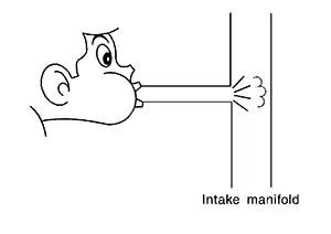
Blow air into each hose and EVAP purge port
 .
. -
Check that air flows freely.
Is the inspection result normal?
YES-1 >>With CONSULT: GO TO 6.
YES-2 >>Without CONSULT: GO TO 7.
NO >>Repair or clean hoses and/or purge port.
-
-
CHECK EVAP CANISTER PURGE VOLUME CONTROL SOLENOID VALVE
With CONSULT-
Start the engine.
-
Perform ŌĆ£PURG VOL CONT/VŌĆØ in ŌĆ£ACTIVE TESTŌĆØ mode of ŌĆ£ENGINEŌĆØ using CONSULT. Check that engine speed varies according to the valve opening.
Does engine speed vary according to the valve opening?
YES >>GO TO 8.
NO >>GO TO 7.
-
-
CHECK EVAP CANISTER PURGE VOLUME CONTROL SOLENOID VALVE
Check the EVAP canister purge volume control solenoid valve. Refer to Component Inspection.
Is the inspection result normal?
YES >>GO TO 8.
NO >>Replace EVAP canister purge volume control solenoid valve. Refer to Exploded View.
-
CHECK EVAP CONTROL SYSTEM PRESSURE SENSOR CONNECTOR
-
Disconnect EVAP control system pressure sensor harness connector.
-
Check that water is not inside connectors.
Is the inspection result normal?
YES >>GO TO 9.
NO >>Replace EVAP control system pressure sensor. Refer to Exploded View.
-
-
CHECK EVAP CONTROL SYSTEM PRESSURE SENSOR FUNCTION
Refer to DTC Description for DTC P0452, refer to DTC Description for DTC P0453.
Is the inspection result normal?
YES >>GO TO 10.
NO >>Replace EVAP control system pressure sensor. Refer to Exploded View.
-
CHECK RUBBER TUBE FOR CLOGGING
-
Disconnect rubber tube connected to EVAP canister vent control valve.
-
Check the rubber tube for clogging.
Is the inspection result normal?
YES >>GO TO 11.
NO >>Clean the rubber tube using an air blower.
-
-
CHECK EVAP CANISTER VENT CONTROL VALVE
Check the EVAP canister vent control valve. Refer to Component Inspection.
Is the inspection result normal?
YES >>GO TO 12.
NO >>Replace EVAP canister vent control valve. Refer to Exploded View.
-
CHECK EVAP PURGE LINE
Inspect EVAP purge line (pipe and rubber tube). Check for evidence of leaks.
Is the inspection result normal?
YES >>GO TO 13.
NO >>Repair or replace malfunctioning part.
-
CLEAN EVAP PURGE LINE
Clean EVAP purge line (pipe and rubber tube) using air blower.
>>INSPECTION END
Other materials:
Trunk Lid Opener Actuator
Component Function Check
Component Function Check
CHECK FUNCTION
CONSULT
Select "Trunk/back door" in "Active Test" mode of
"BCM(TRUNK)".
Select ŌĆ£OnŌĆØ to check tha ...
Power Supply and Ground Circuit (ecm)
Diagnosis Procedure
Diagnosis Procedure
CHECK THE BATTERY CABLE
Turn ignition switch OFF.
Check the battery cable for tightening
enough.
Note:
Check the continuity between the
battery ...
Body Control System. Preparation. Preparation. Special Service Tool
Preparation. Special Service Tool
Special Service Tool
Special Service Tool
The actual shape of the tools may differ from those
illustrated here.
Tool number
(TechMate No.)
Tool name
...