Nissan Sentra B18 (2020-2025) Service Manual: P014d A/f Sensor 1
Dtc Description
To judge malfunctions, this diagnosis measures response time of the A/F signal computed by ECM from the A/F sensor 1 signal. The time is compensated by engine operating (speed and load), fuel feedback control constant, and the A/F sensor 1 temperature index. Judgment is based on whether the compensated time (the A/F signal cycling time index) is inordinately long or not.
DTC DETECTION LOGIC
|
DTC |
CONSULT screen terms (Trouble diagnosis content) |
DTC detection condition |
|
|
P014D |
A/F SENSOR1 (B1) (O2 sensor slow response - lean to rich bank 1 sensor 1) |
Diagnosis condition |
— |
|
Signal (terminal) |
A/F sensor 1 signal |
||
|
Threshold |
The response time of a A/F sensor 1 signal delays more than the specified time computed by ECM |
||
|
Diagnosis delay time |
— |
||
POSSIBLE CAUSE
-
Harness or connectors (The A/F sensor 1 circuit is open or shorted.)
-
A/F sensor 1
FAIL-SAFE
Not applicable
Confirmation Procedure
-
PRECONDITIONING
If DTC Confirmation Procedure has been previously conducted, always perform the following procedure before conducting the next test.
-
Turn ignition switch OFF and wait at least 10 seconds.
-
Turn ignition switch ON.
-
Turn ignition switch OFF and wait at least 10 seconds.
TESTING CONDITION:
Before performing the following procedure, confirm that battery voltage is more than 11 V at idle.
Do you have CONSULT?
YES >>GO TO 2.
NO >>GO TO 6.
-
-
PERFORM DTC CONFIRMATION PROCEDURE-1
 With CONSULT
-
Start engine and warm it up to normal operating temperature.
-
Turn ignition switch OFF and wait at least 10 seconds.
-
Turn ignition switch ON.
-
Turn ignition switch OFF and wait at least 10 seconds.
-
Start engine and keep the engine speed between 3,500 and 4,000 rpm for at least 1minute under no load.
-
Let engine idle for 1 minute.
-
Increase the engine speed up to about 3,600 rpm and keep it for 10 seconds.
-
Fully release accelerator pedal and then let engine idle for about 1 minute.
-
Check the items status of “DATA MONITOR” as follows.
Note:
If “PRSNT” changed to “ABSNT”, refer to Component Function Check.
Data monitor item
Status
A/F SEN1 DIAG3 (B1)
PRSNT
Is “PRSNT” displayed on CONSULT screen?
YES >>GO TO 4.
NO >>GO TO 3.
-
-
PERFORM DTC CONFIRMATION PROCEDURE-2
With CONSULTPerform DTC confirmation procedure-1 again.
Is “PRSNT” displayed on CONSULT screen?
YES >>GO TO 4.
NO >>Refer to Component Function Check.
-
PERFORM DTC CONFIRMATION PROCEDURE-2
With CONSULT-
Wait for about 20 seconds at idle.
-
Check the items status of “DATA MONITOR” as follows.
Note:
If “CMPLT” changed to “INCMP”, refer to Component Function Check.
Data monitor item
Status
A/F SEN1 DIAG1 (B1)
CMPLT
A/F SEN1 DIAG2 (B1)
Is “CMPLT” displayed on CONSULT screen?
YES >>GO TO 5.
NO >>Refer to DTC Diagnosis Procedure.
-
-
PERFORM SELF-DIAGNOSIS
With CONSULTCheck the “SELF-DIAG RESULT”.
Is any DTC detected?
YES >>Proceed to DTC Diagnosis Procedure.
NO >>INSPECTION END
-
CHECK AIR-FUEL RATIO SELF-LEARNING VALUE
 With GST
-
Start engine and warm it up to normal operating temperature.
-
Select Service $01 with GST.
-
Calculate the total value of “Short term fuel trim” and “Long term fuel trim” indications.
Is the total percentage within ±15%?
YES >>GO TO 8.
NO >>GO TO 7.
-
-
DETECT MALFUNCTIONING PART
Check the following.
-
Intake air leaks
-
Exhaust gas leaks
-
Incorrect fuel pressure
-
Lack of fuel
-
Fuel injector
-
Incorrect PCV hose connection
-
PCV valve
-
Mass air flow sensor
Repair or replace malfunctioning part.
-
-
PERFORM DTC CONFIRMATION PROCEDURE
-
Turn ignition switch OFF and wait at least 10 seconds.
-
Turn ignition switch ON.
-
Turn ignition switch OFF and wait at least 10 seconds.
-
Start engine and keep the engine speed between 3,500 and 4,000 rpm for at least 1 minute under no load.
-
Let engine idle for 1 minute.
-
Increase the engine speed up to about 3,600 rpm and keep it for 10 seconds.
-
Fully release accelerator pedal and then let engine idle for about 1 minute.
-
Check 1st trip DTC.
Is 1st trip DTC detected?
YES >>Proceed to DTC Diagnosis Procedure.
NO-1 >>To check malfunction symptom before repair: Refer to Intermittent Incident.
NO-2 >>Confirmation after repair: INSPECTION END
-
Dtc Diagnosis Procedure
-
RETIGHTEN A/F SENSOR 1
Loosen and retighten the A/F sensor 1. Refer to Exploded View.
>>GO TO 2.
-
CHECK EXHAUST GAS LEAK
-
Start engine and run it at idle.
-
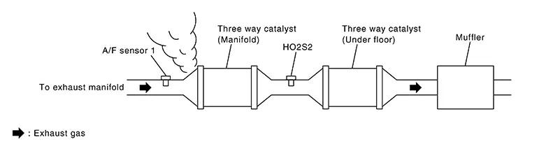
Listen for an exhaust gas leak before three way catalyst (manifold).
Is exhaust gas leak detected?
YES >>Repair or replace.
NO >>GO TO 3.
-
-
CHECK FOR INTAKE AIR LEAK
Listen for an intake air leak after the mass air flow sensor.
Is intake air leak detected?
YES >>Repair or replace.
NO >>GO TO 4.
-
CLEAR THE MIXTURE RATIO SELF-LEARNING VALUE
-
Clear the mixture ratio self-learning value. Refer to Work Procedure.
-
Run engine for at least 10 minutes at idle speed.
Is the 1st trip DTC P0171 or P172 detected? Is it difficult to start engine?
YES >>Perform trouble diagnosis for DTC P0171 or P0172. Refer to DTC Description. or Refer to DTC Description.
NO >>GO TO 5.
-
-
CHECK AIR FUEL RATIO (A/F) SENSOR 1 POWER SUPPLY
-
Disconnect A/F sensor 1 harness connector.
-
Turn ignition switch ON.
-
Check the voltage between A/F sensor 1 harness connector and ground.
+
–
Voltage
A/F sensor 1
Connector
Terminal
F12
4
Ground
Battery voltage
Is the inspection result normal?
YES >>GO TO 6.
NO >>Repair or replace error-detected parts.
-
-
CHECK A/F SENSOR 1 INPUT SIGNAL CIRCUIT
-
Turn ignition switch OFF.
-
Disconnect ECM harness connector.
-
Check the continuity between A/F sensor 1 harness connector and ECM harness connector.
A/F sensor 1
ECM
Continuity
Connector
Terminal
Connector
Terminal
F12
1
F25
86
Existed
2
88
-
Check the continuity between A/F sensor 1 harness connector and ground, or ECM harness connector and ground.
A/F sensor 1
—
Continuity
Connector
Terminal
F12
1
Ground
Not existed
2
ECM
—
Continuity
Connector
Terminal
F25
86
Ground
Not existed
88
-
Also check harness for short to power.
Is the inspection result normal?
YES >>GO TO 7.
NO >>Repair or replace error-detected parts.
-
-
CHECK AIR FUEL RATIO (A/F) SENSOR 1 HEATER
Refer to Component Inspection.
Is the inspection result normal?
YES >>GO TO 8.
NO >>GO TO 10.
-
CHECK MASS AIR FLOW SENSOR
Refer to Component Inspection.
Is the inspection result normal?
YES >>GO TO 9.
NO >>Replace mass air flow sensor. Refer to Exploded View.
-
CHECK PCV VALVE
Refer to POSITIVE CRANKCASE VENTILATION : Periodic Maintenance.
Is the inspection result normal?
YES >>GO TO 10.
NO >>Repair or replace PCV valve. Refer to Component Parts Location.
-
REPLACE AIR FUEL RATIO (A/F) SENSOR 1
Replace air fuel ratio (A/F) sensor 1.Refer to Exploded View.
CAUTION:
-
Discard any A/F sensor which has been dropped from a height of more than 0.5 m (19.7 in) onto a hard surface such as a concrete floor; use a new one.
-
Before installing new A/F sensor, clean exhaust system threads.
INSPECTION END
-
 P014c A/f Sensor 1
Dtc Description
DTC Description
To judge malfunctions, this diagnosis measures response time of
the A/F signal computed by ECM from the A/F sensor 1 signal. The time is
compensated by eng ...
 P015a A/f Sensor 1
Dtc Description
DTC Description
To judge malfunctions, this diagnosis measures response time of
the A/F signal computed by ECM from the A/F sensor 1 signal. The time is
compensated by eng ...
Other materials:
Optical Sensor Circuit
Component Function Check
Component Function
Check
CHECK OPTICAL SENSOR SIGNAL
Ignition switch ON.
Turn lighting switch AUTO.
With the optical sen ...
P0963 Pressure control solenoid A
DTC Logic
DTC DETECTION LOGIC
DTC
CONSULT screen terms
(Trouble diagnosis content)
DTC detection condition
Possible causes
P0963
PC SOLENOID A
(Pressure Control Solenoid A
Control Circuit High)
The line pressure solenoid valve current is 200
mA or less c ...
Normal Operating Condition
Description
Description
AUTO LIGHT SYSTEM
The headlamps (both sides) may not turn ON/OFF
immediately after passing a dark area or bright area (short tunnel,
sky bridge, shadowed area etc.) while using the auto light system.
This is normal.
HIGH BEAM ASSIST SYSTEM
When driving ...
