Nissan Sentra Service Manual: P0963 Pressure control solenoid A
DTC Logic
DTC DETECTION LOGIC
| DTC | CONSULT screen terms (Trouble diagnosis content) | DTC detection condition | Possible causes |
| P0963 | PC SOLENOID A (Pressure Control Solenoid A Control Circuit High) | The line pressure solenoid valve current is 200
mA or less continuously for 200 msec or more
under the following diagnosis conditions: Diagnosis conditions
|
|
DTC CONFIRMATION PROCEDURE
1.PREPARATION BEFORE WORK
If another “DTC CONFIRMATION PROCEDURE” occurs just before, turn ignition switch OFF and wait for at least 10 seconds, then perform the next test.
>> GO TO 2.
2.CHECK DTC DETECTION
- Start the engine and wait for 5 seconds or more.
- Check the first trip DTC.
Is “P0963” detected? YES >> Go to TM-203, "Diagnosis Procedure".
NO >> INSPECTION END
Diagnosis Procedure
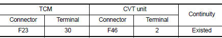
1.CHECK CIRCUIT BETWEEN TCM AND CVT UNIT
- Turn ignition switch OFF.
- Disconnect TCM connector and CVT unit connector.
- Check continuity between TCM harness connector terminal and CVT unit harness connector terminal.
Is the inspection result normal? YES >> GO TO 2.
NO >> Repair or replace malfunctioning parts.
2.CHECK LINE PRESSURE SOLENOID VALVE
Check line pressure solenoid valve. Refer to TM-203, "Component Inspection".
Is the inspection result normal? YES >> Check intermittent incident. Refer to GI-39, "Intermittent Incident".
NO >> Repair or replace malfunctioning parts.
Component Inspection
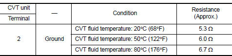
1.CHECK LINE PRESSURE SOLENOID VALVE
Check resistance between CVT unit connector terminal and ground.
 Is the inspection
result normal?
YES >> INSPECTION END
NO >> There is a malfunction of line pressure solenoid valve. Replace transaxle assembly. Refer to TM- 283, "Removal and Installation".
 P0962 Pressure control solenoid A
DTC Logic
DTC DETECTION LOGIC
DTC
CONSULT screen terms
(Trouble diagnosis content)
DTC detection condition
Possible causes
P0962
PRESSURE CONTROL SOLENOID
A
(Pre ...
 P0965 Pressure control solenoid B
DTC Logic
DTC DETECTION LOGIC
DTC
CONSULT screen terms
(Trouble diagnosis content)
DTC detection condition
Possible causes
P0965
PC SOLENOID B
(Pressure control sol ...
Other materials:
Abs branch line circuit
Diagnosis procedure
1.Check connector
Turn the ignition switch OFF.
Disconnect the battery cable from the negative terminal.
Check the terminals and connectors of the abs actuator and electric unit
(control unit) for damage, bend
and loose connection (unit side and connector side).
...
Using the system
The NISSAN Voice Recognition system allows
hands-free operation of the Bluetooth® Phone
System.
If the vehicle is in motion, some commands may
not be available so full attention may be given to
vehicle operation.
Initialization
When the ignition switch is placed in the ON
position, NISSAN ...
Keyfob (if so equipped)
Replace the battery in the keyfob as follows:
Remove the screw A .
Insert a small screwdriver into the slit of the
corner B and twist it to separate the upper
part from the lower part. Use a cloth to
protect the casing.
Replace the battery with a new one.
Do not touch the int ...
