Nissan Sentra Service Manual: Main line between ipdm-e and dlc circuit
Diagnosis procedure
1.Check connector
- Turn the ignition switch off.
- Disconnect the battery cable from the negative terminal.
- Check the following terminals and connectors for damage, bend and loose connection (connector side and harness side).
- Harness connector e4
- Harness connector m2
Is the inspection result normal? Yes >> go to 2.
No >> repair the terminal and connector.
2.Check harness continuity (open circuit)
- Disconnect the following harness connectors.
- Ipdm e/r
- Harness connectors e4 and m2
- Check the continuity between the ipdm e/r harness connector and the harness connector.
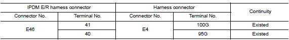
Is the inspection result normal? Yes >> go to 3.
No >> repair the main line between the ipdm e/r and the harness connector e4.
3.Check harness continuity (open circuit)
Check the continuity between the harness connector and the data link connector.
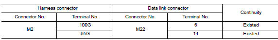
Is the inspection result normal? Yes (present error)>>check can system type decision again.
Yes (past error)>>error was detected in the main line between the ipdm e/r and the data link connector.
No >> repair the main line between the harness connector m2 and the data link connector.
 Can system (type 3)
Dtc/circuit diagnosis ...
 Main line between dlc and av circuit
Diagnosis procedure
1.Check harness continuity (open circuit)
Turn the ignition switch off.
Disconnect the battery cable from the negative terminal.
Disconnect the following harness connector ...
Other materials:
Fuel injector
Component Function Check
1.INSPECTION START
Turn ignition switch to START.
Is any cylinder ignited?
YES >> GO TO 2.
NO >> Proceed to EC-450, "Diagnosis Procedure".
2.CHECK FUEL INJECTOR FUNCTION
With CONSULT
Start engine.
Perform “POWER BALANCE” in Р...
Washer tank
Exploded view
Washer tank inlet
Washer tank
Washer level switch
Washer tank seal
Washer pump
Removal and installation
REMOVAL
Drain the washer fluid.
Remove the front under cover. Refer to ext-30, "front under cover :
removal and installation".
Remove the fe ...
P099C Shift solenoid G
DTC Logic
DTC
CONSULT screen terms
(Trouble diagnosis content)
DTC detection condition
Possible causes
P099C
SHIFT SOLENOID G
(Shift Solenoid G Control Circuit
High)
The TCM high clutch & reverse brake solenoid
valve current monitor reading is 200 mA ...
