Nissan Sentra B18 (2020-2025) Service Manual: Ignition Signal
Component Function Check
Component Function Check
-
INSPECTION START
Turn ignition switch OFF, and restart engine.
Does the engine start?
YES-1 >>With CONSULT: GO TO 2.
YES-2 >>Without CONSULT: GO TO 3.
NO >>Refer to Diagnosis Procedure.
-
CHECK IGNITION SIGNAL FUNCTION-1
 With CONSULT
-
Perform ŌĆ£POWER BALANCEŌĆØ in ŌĆ£ACTIVE TESTŌĆØ mode of ŌĆ£ENGINEŌĆØ with CONSULT.
-
Check that each circuit produces a momentary engine speed drop.
Is the inspection result normal?
YES >>INSPECTION END
NO >>Refer to Diagnosis Procedure.
-
-
CHECK IGNITION SIGNAL FUNCTION-2
 Without CONSULT
-
Let engine idle.
-
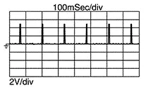
Read the voltage signal between ECM harness connector terminals with an oscilloscope.
Note:ECM
Voltage signal
+
ŌłÆ
Connector
Terminal
Connector
Terminal
F25
109
E16
162
106
105
103

The pulse cycle changes depending on rpm at idle.
Is the inspection result normal?
YES >>INSPECTION END
NO >>Refer to Diagnosis Procedure.
-
Diagnosis Procedure
Diagnosis Procedure
-
CHECK IGNITION COIL POWER SUPPLY
-
Turn ignition switch OFF.
-
Disconnect ignition coil harness connector.
-
Turn ignition switch ON.
-
Check the voltage between ignition coil harness connector and ground.
+
ŌłÆ
Voltage
Ignition coil
Cylinder
Connector
Terminal
1
F34
3
Ground
Battery voltage
2
F35
3
3
F36
3
4
F37
3
Is the inspection result normal?
YES >>GO TO 5.
NO >>GO TO 2.
-
-
CHECK FUSE
-
Turn ignition switch OFF.
-
Pull out No. 80fuse (15 A) and check that the fuse is not blowing.
Is the inspection result normal?
YES >>GO TO 3.
NO >>Replace the fuse after repairing the applicable circuit.
-
-
CHECK IGNITION COIL POWER SUPPLY CIRCUIT
-
Turn ignition switch OFF.
-
Disconnect IPDM E/R harness connector.
-
Check the continuity between IPDM E/R harness connector and condenser harness connector.
IPDM E/R
Condenser
Continuity
Connector
Terminal
Connector
Terminal
F96
66
F8
1
Existed
-
Check harness for short to ground and to power.
Is the inspection result normal?
YES >>GO TO 4.
NO >>Repair or replace error-detected parts.
-
-
CHECK IPDM E/R POWER SUPPLY AND GROUND CIRCUIT
Check IPDM E/R power supply and ground circuit. Refer to Diagnosis Procedure(with I-key) Refer to Diagnosis Procedure(with out I-key). Diagnosis Procedure.
Is the inspection result normal?
YES >>Replace IPDM E/R. Refer to Removal and Installation(with I-key) Refer to Removal and Installation(with out I-key).
NO >>Repair or replace error-detected parts.
-
CHECK IGNITION COIL GROUND
-
Turn ignition switch OFF.
-
Check the continuity between ignition coil harness connector and ground.
+
ŌłÆ
Continuity
Ignition coil
Cylinder
Connector
Terminal
1
F34
2
Ground
Existed
2
F35
2
3
F36
2
4
F37
2
Is the inspection result normal?
YES >>GO TO 6.
NO >>Repair or replace error-detected parts.
-
-
CHECK IGNITION SIGNAL CIRCUIT
-
Disconnect ECM harness connector.
-
Check the continuity between ignition coil harness connector and ECM harness connector.
Ignition coil
ECM
Continuity
Cylinder
Connector
Terminal
Connector
Terminal
1
F34
1
F25
109
Existed
2
F35
1
106
3
F36
1
105
4
F37
1
103
-
Also check harness for short to ground and to power.
Is the inspection result normal?
YES >>GO TO 7.
NO >>Repair or replace error-detected parts.
-
-
CHECK IGNITION COIL WITH POWER TRANSISTOR
Check ignition coil with power transistor. Refer to Component Inspection.
Is the inspection result normal?
YES >>INSPECTION END
NO >>Replace malfunctioning ignition coil with power transistor. Refer to Removal and Installation.
Other materials:
Squeak and Rattle Trouble Diagnoses
Work Flow
Work Flow
CUSTOMER INTERVIEW
Interview the customer if possible, to determine
the conditions that exist when the noise occurs. Use the Diagnostic
Worksheet during the interview to document the facts and conditions
when the noise occurs and any customer's comments; refer ...
Cooling Fan
Exploded View
Exploded View
1.
Reservoir tank
cap
2.
Reservoir tank
3.
...
Trip computer
1. Vehicle speed
The vehicle speed screen shows the current speed of the Nissan Sentra as well
as the average vehicle speed calculated since the last reset.
Average vehicle speed:
Press the OK button on the steering wheel to open the drive computer Reset menu,
then follow the on-screen in ...