Nissan Sentra B18 (2020-2025) Service Manual: Heater & Air Conditioning System :: System Description. Refrigeration System
Refrigeration System. Component Part Location
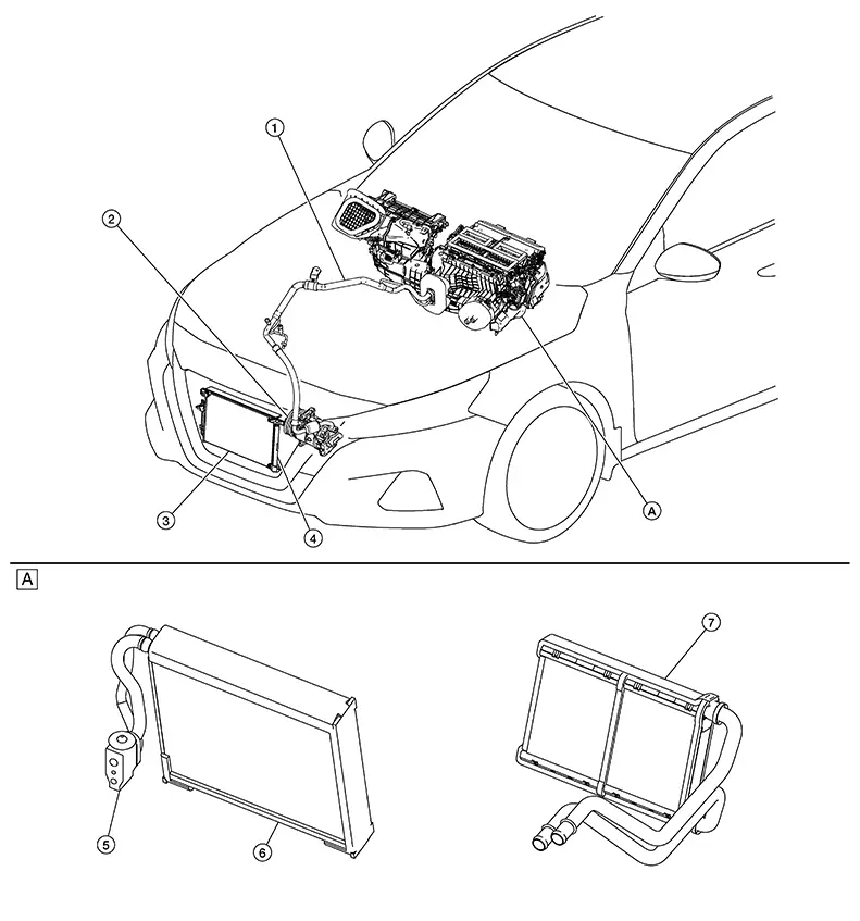
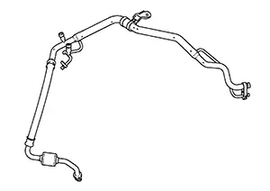
Component Part Location
|
1. |
Internal heat exchanger |
Refer to Internal Heat Exchanger. |
|
2. |
Compressor |
Refer to Compressor. |
|
3. |
Condenser |
Refer to Condenser. |
|
4. |
Liquid tank |
Refer to Liquid Tank. |
|
5. |
Expansion valve |
Refer to Expansion Valve. |
|
6. |
Evaporator |
Refer to Evaporator. |
|
7. |
Heater core |
Refer to Heater Core. |
|
A |
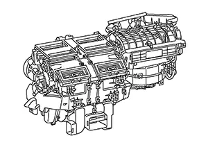
Heating and cooling unit assembly |
Refer to Heating and Cooling Unit Assembly. |
Heating and Cooling Unit Assembly
Heating and Cooling Unit Assembly
This unit combines the blower unit, heating unit, and cooling unit into an assembly.
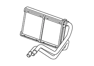
Heater Core
Heater Core
Hot coolant from the engine is passed through a winding tube of the core. Fins attached to the core tubes serve to increase surface for heat transfer to air that is forced past them, by a fan, thereby heating the passenger compartment.
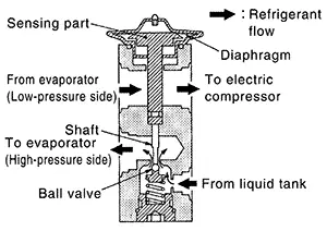
Expansion Valve
Expansion Valve
The refrigerant temperature is detected by the temperature sensing part located in low-pressure refrigerant path inside expansion valve. The lift amount of high-pressure side ball valve is changed to regulate the refrigerant flow.
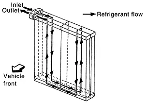
Evaporator
Evaporator
-
A thin laminate pipeless evaporator is used.
-
The mist from liquid refrigerant transforms to gas by evaporation by the air conveyed from blower motor. The air is cooled by the heat by evaporation.
Compressor
Compressor
Intakes, compresses, and discharges refrigerant to circulate refrigerant inside the refrigerant cycle.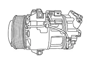
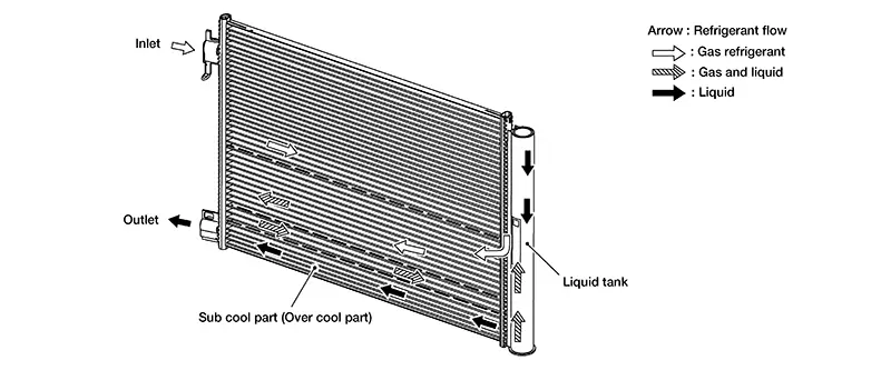
Condenser
Condenser
The sub-cool section further cools the liquid refrigerant, increasing the amount of heat that the liquid refrigerant can absorb and improving cooling performance.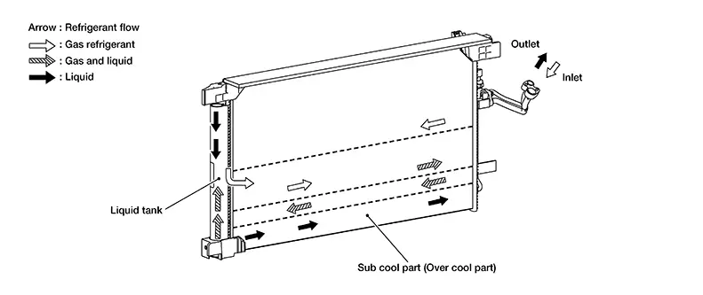
Liquid Tank
Liquid Tank
-
A liquid tank compatible with R-1234yf refrigerant is used.
-
Eliminates foreign matter in refrigerant and temporarily stores liquid refrigerant.
Internal Heat Exchanger
Internal Heat Exchanger
Transfers heat out of the liquid refrigerant, sub cooling it below condensation temperature.
Refrigerant Cycle
Refrigerant Cycle
Refrigerant flow
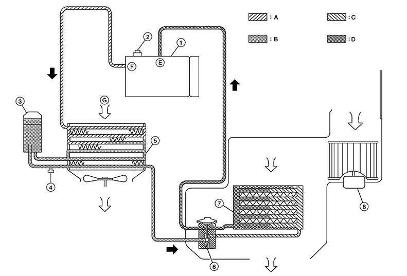
|
1. |
Electric compressor |
2. |
Pressure relief valve |
3. |
Liquid tank |
|
4. |
Refrigerant pressure sensor |
5. |
Condenser |
6. |
Expansion valve |
|
7. |
Evaporator |
8. |
Blower motor |
A. |
High-pressure gas |
|
B. |
High-pressure liquid |
C. |
Low-pressure liquid |
D. |
Low-pressure gas |
|
E. |
Suction port |
F. |
Discharge port |
G. |
Outside air |
Refrigerant Flow
The refrigerant from the compressor flows through the condenser and liquid tank, the evaporator and returns to the compressor. The refrigerant evaporation in the evaporator is controlled by an expansion valve.
Freeze Protection
To prevent the evaporator from freezing up, the evaporator air temperature is monitored by the intake sensor and the voltage signal to the A/C auto amp. makes the A/C relay go OFF and stop the compressor.
Refrigerant System Protection
Refrigerant System Protection
Refrigerant pressure sensor
The refrigerant system is protected against excessively high or low pressures by the refrigerant pressure sensor, located on the high-pressure pipe. If the system pressure rises above or falls below the specifications, the refrigerant pressure sensor detects the pressure inside the refrigerant line and sends the voltage signal to the ECM. The ECM then ceases to supply power to the A/C relay which disengages and stops the compressor when pressure on the high pressure side (as detected by refrigerant pressure sensor) is over approximately 1,520 kPa (15.5 kg/cm2, 220.4 psi), or below approximately 182 kPa (1.86 kg/cm2, 26.39 psi).
Pressure Relief Valve
The refrigerant system is also protected by a pressure relief valve, located in the rear head of the compressor. When the pressure of refrigerant in the system increases to an abnormal level [more than 3,010 kPa (30.7 kg/cm2, 436.45 psi)], the release port on the pressure relief valve automatically opens and releases refrigerant into the atmosphere.
Other materials:
Squeak and Rattle Trouble Diagnoses
Work Flow
Work Flow
CUSTOMER INTERVIEW
Interview the customer if possible, to determine
the conditions that exist when the noise occurs. Use the Diagnostic
Worksheet during the interview to document the facts and conditions
when the noise occurs and any customer's comments; refer ...
System Settings Cannot Be Turned On/off
Diagnosis Procedure
Diagnosis Procedure
CHECK SYSTEM SETTING
Turn ignition switch ON.
Check that the each system settings is
selectable on the combination meter.
Is the inspection result norma ...
Trip computer
1. Vehicle speed
The vehicle speed screen shows the current speed of the Nissan Sentra as well
as the average vehicle speed calculated since the last reset.
Average vehicle speed:
Press the OK button on the steering wheel to open the drive computer Reset menu,
then follow the on-screen in ...