Nissan Sentra Service Manual: General Precaution
WARNING:
When replacing fuel line parts, be sure to observe the following.
- Put a “CAUTION: FLAMMABLE” sign in the work area.
- Be sure to work in a well ventilated area and have a CO2 fire extinguisher.
- Do not smoke while working on the fuel system. Keep open flames and sparks away from the work area.
CAUTION:
- Before removing fuel line parts, carry out the following procedures:
- Put drained fuel in an explosion-proof container and put the lid on securely. Keep the container in safe area.
- Release fuel pressure from the fuel lines. Refer to EC-49, "EVAPORATIVE EMISSION SYSTEM : System Description".
- Disconnect the battery ground cable.
- Always replace O-rings and clamps with new ones.
- Do not kink or twist tubes when they are being installed.
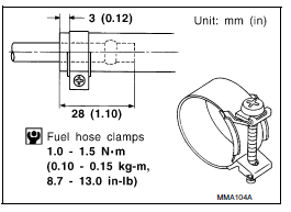
- Do not tighten hose clamps excessively to avoid damaging hoses.
Tighten high-pressure rubber hose clamp so that clamp end is 3 mm (0.12 in) from hose end.
Tightening torque specifications are the same for all rubber hose clamps.
Ensure that screw does not contact adjacent parts.
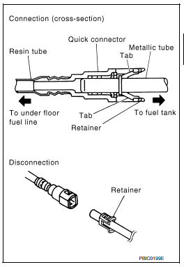
- After connecting the fuel tube quick connectors, make sure
the quick connectors are secure.
Check that the connector and resin tube do not contact any adjacent parts.
- Apply fuel pressure to the fuel system by turning the ignition switch to ON (without starting the engine). Then check for fuel leaks at the fuel tube connections.
- Start the engine and rev the engine, then check for fuel leaks at the fuel tube connections.
- After installing the tubes, run the engine and check for fuel leaks at the connections.
- Use only a Genuine NISSAN fuel filler cap as a replacement. If an incorrect fuel filler cap is used, the MIL may come on.
- For servicing “Evaporative Emission System” parts, refer to EC-49, "EVAPORATIVE EMISSION SYSTEM : System Description".
 Precaution for Supplemental Restraint System (SRS) "AIR BAG" and "SEAT BELT
PRE-TENSIONER"
Precaution for Supplemental Restraint System (SRS) "AIR BAG" and "SEAT BELT
PRE-TENSIONER"
The Supplemental Restraint System such as “AIR BAG” and “SEAT BELT
PRE-TENSIONER”, used along
with a front seat belt, helps to reduce the risk or severity of injury to the
dri ...
 Preparation
Special Service Tool
The actual shape of the tools may differ from those illustrated here.
Commercial Service Tool
...
Other materials:
B0001, B0002 Driver airbag module
Description
DTC B0001, B0002 DRIVER AIRBAG MODULE
The driver air bag module is dual stage and is wired to the air bag diagnosis
sensor unit through the spiral
cable. The air bag diagnosis sensor unit will monitor for opens and shorts in
detected lines to the driver air bag
module including t ...
Dtc/circuit diagnosis
Sport mode switch
Component function check
1. Check sport mode switch operation
Turn ignition switch on.
Check SPORT mode indicator lamp turns ON/OFF on combination meter when
turn SPORT mode switch
ON/OFF.
Is the inspection result normal?
Yes >> go to 2.
No >> procee ...
C1604 Torque sensor
DTC Logic
DTC DETECTION LOGIC
DTC
Display item
Malfunction detected condition
Possible cause
C1604
TORQUE SENSOR
When torque sensor output signal is malfunctioning
Harness or connector
Torque sensor
EPS control unit
DTC CONFIRMATION ...
