Nissan Sentra Service Manual: G Sensor
Exploded View
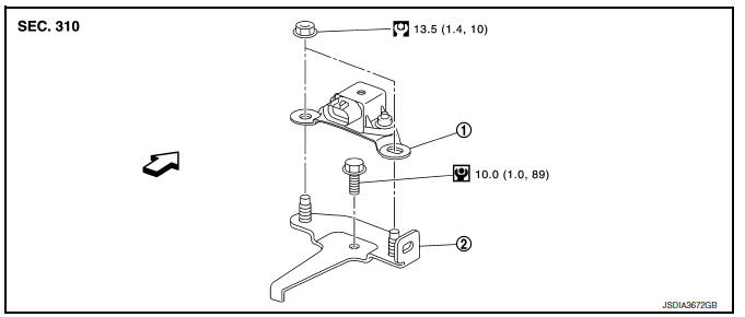
- G sensor
- Bracket
 Vehicle front
 NВ·m (kg-m, ft-lb)
 NВ·m (kg-m, in-lb)
Removal and Installation
WARNING:
Do not leave any objects (screwdrivers, tools, etc.) on the seat during seat repair. It can lead to personal injury if the side air bag module should accidentally deploy.
CAUTION:
- Do not drop or strike G sensor, because it has little tolerance for impact.
- Do not use a power tool and avoid impact.
REMOVAL
- Disconnect the negative and positive battery terminals and wait at least three minutes. Refer to PG-50, "Removal and Installation (Battery)".
- Remove driver seat. Refer to SE-18, "DRIVER SIDE : Removal and Installation - Seat Assembly".
- Remove center pillar lower garnish (left side) and dash side finisher (left side). Refer to INT-27, "CENTER PILLAR LOWER FINISHER : Removal and Installation" (center pillar lower garnish) and INT-26, "DASH SIDE FINISHER : Removal and Installation" (dash side finisher).
- Pull up floor carpet. Refer to INT-35, "Removal and Installation".
- Disconnect G sensor harness connector.
- Remove G sensor.
- Remove bracket.
INSTALLATION
Installation is the reverse order of removal.
Adjustment
ADJUSTMENT AFTER INSTALLATION
Perform “CALIBRATION OF G SENSOR”. Refer to TM-147, "Description".
 AIR Breather hose
Exploded View
Harness bracket
Clip
Air breather hose
Vehicle front
Always replace after every
disassembly.
Removal and Installation
REMOVAL
Remove clips from harness bracke ...
 OIL PAN
Exploded View
Transaxle assembly
Oil pan gasket
Magnet
Oil pan
Overflow tube
Drain plug gasket
Drain plug
Oil pan fitting bolt
: Always replace after every
disassembly.
: ...
Other materials:
2135 TP Sensor
DTC Logic
DTC DETECTION LOGIC
NOTE:
If DTC P2135 is displayed with DTC P0643, first perform the trouble
diagnosis for DTC P0643. Refer to
EC-353, "DTC Logic".
DTC No.
CONSULT screen terms
(Trouble diagnosis content)
DTC detecting condition
Possible cause
...
Operating tips
CAUTION
Do not use alcohol, benzine or thinner
to clean the camera. This will cause
discoloration. To clean the camera,
wipe with a cloth dampened with a diluted
mild cleaning agent and then wipe
with a dry cloth.
Do not damage the camera as the monitor
screen may be adversely affe ...
Wiring diagram
Tire pressure monitoring system
With intelligent key
WITH INTELLIGENT KEY : Wiring Diagram
Without intelligent key
WITHOUT INTELLIGENT KEY : Wiring Diagram
...
