Nissan Sentra B18 (2020-2025) Service Manual: Fuel Level Sensor Signal Circuit
Component Function Check
Component Function Check
-
COMBINATION METER INPUT SIGNAL
-
 CONSULT
-
Select “FUEL METER” in “Data Monitor” mode of “METER/M&A”.
-
Compare the “FUEL METER” value and the fuel gauge reading of the combination meter. Fuel gauge and data monitor indications should be close.
Fuel gauge indication position
Reference value of data monitor [L]
1
Approx. 45.8
3/4
Approx. 35.4
1/2
Approx. 24.6
1/4
Approx. 12.4
0
Approx. 2.9
-
Does monitor value match fuel gauge reading?
YES >>Inspection End.
NO >>Replace combination meter. Refer to Removal and Installation.
-
Diagnosis Procedure
Diagnosis Procedure
-
CHECK HARNESS CONNECTOR
-
-
Ignition switch OFF.
-
Check combination meter and fuel level sensor unit and fuel pump (fuel level sensor) terminals (meter-side and harness-side) for poor connection.
-
Is the inspection result normal?
YES >>GO TO 2.
NO >>Repair or replace harness or connector.
-
-
CHECK FUEL LEVEL SENSOR UNIT CIRCUIT
-
-
Disconnect combination meter harness connector and fuel level sensor unit and fuel pump (fuel level sensor) harness connector.
-
Check continuity between combination meter harness connector and fuel level sensor unit and fuel pump (fuel level sensor) harness connector.
Combination meter
Fuel level sensor unit and fuel pump (fuel level sensor)
Continuity
Connector
Terminal
Connector
Terminal
M24
35
B48
3
Yes
-
Check continuity between fuel level sensor unit and fuel pump (fuel level sensor) harness connector and ground.
Fuel level sensor unit and fuel pump (fuel level sensor)
—
Continuity
Connector
Terminal
B48
3
Ground
No
-
Is the inspection result normal?
YES >>GO TO 3.
NO >>Repair or replace harness or connector.
-
-
CHECK FUEL LEVEL SENSOR GROUND CIRCUIT
-
-
Check continuity between combination meter harness connector and fuel level sensor unit and fuel pump (fuel level sensor) harness connector.
Combination meter
Fuel level sensor unit and fuel pump (fuel level sensor)
Continuity
Connector
Terminal
Connector
Terminal
M24
36
B48
2
Yes
-
Check continuity between fuel level sensor unit and fuel pump (fuel level sensor) harness connector and ground.
Fuel level sensor unit and fuel pump (fuel level sensor)
—
Continuity
Connector
Terminal
B48
2
Ground
No
-
Is the inspection result normal?
YES>>GO TO 4.
NO>>Repair or replace harness or connector.
-
-
CHECK INSTALLATION CONDITION
-
Check fuel level sensor unit installation, and verify the float arm does not interfere or bind with the internal components in the fuel tank.
Is the inspection result normal?
YES >>Inspection End.
NO >>Install the fuel level sensor unit and fuel pump (fuel level sensor) properly. Refer to Removal and Installation.
-
Component Inspection
Component Inspection
-
CHECK FUEL LEVEL SENSOR UNIT AND FUEL PUMP (FUEL LEVEL SENSOR)
-
-
Remove the fuel level sensor unit and fuel pump (fuel level sensor). Refer to Removal and Installation.
-
Check the resistance between fuel level sensor unit and fuel pump (fuel level sensor) terminals.
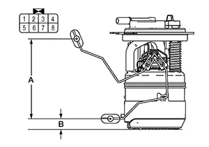
Fuel level sensor unit and fuel pump (fuel level sensor)
Condition
Resistance (Ω)
(Approx.)
Height [mm (in)]
Terminals
2
3
Full* (A)
91
144 (5.67)
Empty* (B)
283.0
19 (0.75)
*: When float rod is contact with stopper.
-
Is the inspection result normal?
YES >>Inspection End.
NO >>Replace fuel level sensor unit and fuel pump (fuel level sensor). Refer to Removal and Installation.
-
Other materials:
Engine Mounting Insulator (rh)
Exploded View
Exploded View
CVT Models
1.
Engine mounting
insulator (LH)
2.
Engine mounting
insula ...
Heated Seat Lh Relay
Component Function Check
Component Function
Check
CHECK HEATED SEAT LH RELAY FUNCTION
Check that seat cushion and seat back warm to the
preset temperature when operating the heated seat switch LH to HIGH
and LOW.
...
Cold weather driving
Freeing a frozen door lock
To help prevent the door locks of your Nissan Sentra from freezing in cold weather,
apply a suitable de-icing agent directly into the keyhole. If a lock does become
frozen, gently warm the mechanical key before inserting it into the keyhole. As
an alternative, use t ...