Nissan Sentra Service Manual: Front wiper auto stop signal circuit
Component function check
1. Check front wiper (auto stop) operation
 Consult data monitor
- Select “WIP AUTO STOP” of IPDM E/R DATA MONITOR item.
- Operate the front wiper.
- With the front wiper operation, check the monitor status.
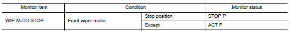
Is the inspection result normal? YES >> Auto stop signal circuit is normal.
NO >> Refer to WW-41, "Diagnosis Procedure".
Diagnosis procedure
Regarding wiring diagram information, refer to ww-24, "wiring diagram - with intelligent key" or ww-29, "wiring diagram - without intelligent key".
1. Check ipdm e/r output voltage
- Turn the ignition switch off
- Disconnect front wiper motor.
- Turn the ignition switch on.
- Check voltage between front wiper motor connector e1 and ground.
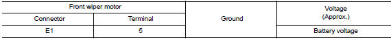
Is the inspection result normal? Yes >> replace front wiper motor. Refer to ww-62, "removal and installation".
No >> go to 2.
2. Check front wiper motor (auto stop) circuit continuity
- Turn the ignition switch OFF
- Disconnect ipdm e/r connector.
- Check continuity between ipdm e/r harness connector e46 and front wiper motor harness connector e1.

- Check continuity between ipdm e/r harness connector e46 and ground.
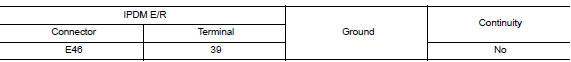
Is the inspection result normal? Yes >> replace ipdm e/r. Refer to pcs-30, "removal and installation" (with intelligent key system) or pcs-58, "removal and installation" (without intelligent key system).
No >> repair or replace the harness or connectors.
 Front wiper motor hi circuit
Component function check
1. Check front wiper hi operation
Ipdm e/r auto active test
Start ipdm e/r auto active test. Refer to ww-15, "diagnosis description"
(with intelligent key ...
 Front wiper motor ground circuit
Diagnosis procedure
Regarding Wiring Diagram information, refer to WW-24, "Wiring Diagram - With
Intelligent Key" or WW-29,
"Wiring Diagram - Without Intelligent Key".
1.Check ...
Other materials:
Basic inspection
Inspection and adjustment
Additional service when replacing control unit (bcm)
Additional service when replacing control unit (bcm) : description
Before replacement
When replacing BCM, save or print current vehicle specification with CONSULT
configuration before replacement.
Note:
If “ ...
Removal and installation
Horn
Exploded view
Horn high
Horn low
Front
Note:
Shown with the front fascia removed for clarity.
Removal and installation
Horn low
Removal
Remove the core support cover. Refer to ext-23, "removal and
installation".
Disconnect the horn low harness connectors. ...
Variable voltage control system
CAUTION
Do not ground accessories directly to
the battery terminal. Doing so will bypass
the variable voltage control system
and the vehicle battery may not
charge completely.
Use electrical accessories with the engine
running to avoid discharging the
vehicle battery.
Your v ...
