Nissan Sentra Service Manual: Front combination lamp
Exploded View
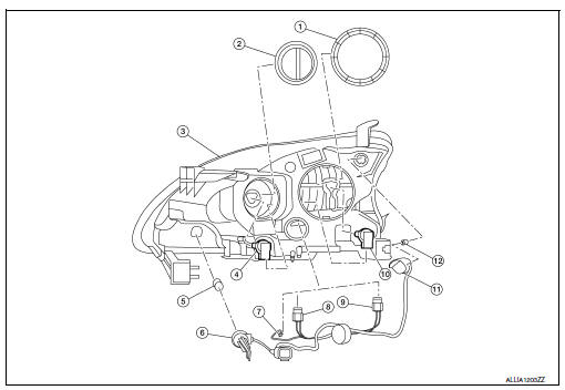
- Large cover (not serviceable)
- Small cover (not serviceable)
- Front combination lamp
- Halogen lamp bulb (high beam)
- Turn signal lamp bulb
- Turn signal lamp bulb socket
- LED harness connector
- Halogen lamp bulb (high beam) harness connector
- Halogen lamp bulb (low beam) harness connector
- Halogen lamp bulb (low beam)
- Side marker lamp bulb socket
- Side marker lamp bulb
Disassembly and Assembly
DISSASSEMBLY
WARNING:
Do not touch bulb while it is lit or right after being turned off. Burning may result.
CAUTION:
- Do not touch glass surface of the bulb with bare hands or allow oil or grease to get on it to prevent damage to bulb.
- Do not leave the bulb out of the lamp reflector for a long time
because dust, moisture, smoke, etc.
may affect the performance of the lamp.
- Remove front combination lamp. Refer to EXL-119, "Removal and Installation".
- Rotate the covers counterclockwise and remove.
- Rotate the halogen lamp bulb (low beam) counterclockwise and remove.
- Disconnect the harness connector from the halogen lamp bulb (low beam) and remove.
- Rotate the halogen lamp bulb (high beam) counterclockwise and remove.
- Disconnect the harness connector from the halogen lamp bulb (high beam) and remove.
- Rotate the side marker bulb socket counterclockwise and remove.
- Remove the side marker bulb from the side marker bulb socket.
- Rotate the turn signal bulb socket counterclockwise and remove.
- Remove the turn signal bulb from the turn signal bulb socket.
- Disconnect the harness connector from the LED circuit board and remove the harness.
ASSEMBLY
Assembly is in the reverse order of disassembly.
CAUTION:
After installing, be sure to install the bulb sockets securely to ensure watertightness.
Revision:

 Rear combination lamp
Exploded View
Rear combination lamp
Rear turn signal lamp bulb
Rear turn signal lamp socket
LED lamp harness connector
Rear combination lamp harness
connector
Back-up lamp bulb s ...
Other materials:
Supplemental air bag warning light
The supplemental air bag warning light,
displaying in the instrument panel,
monitors
the circuits for the air bag systems, pretensioners
and all related wiring.
When the ignition switch is placed in the ON or
START position, the supplemental air bag warning
light illuminates for about ...
Service Notice and Precautions for TPMS
WARNING:
Radio waves could adversely affect electric medical equipment. Those
who use a pacemaker should
contact the electric medical equipment manufacturer for the possible influences
before use.
Low tire pressure warning lamp blinks for 1 minute, then turns ON when
occurring any malfu ...
B0028 Side airbag module RH
Description
DTC B0028 FRONT RH SIDE AIR BAG MODULE
The front RH side air bag module is wired to the air bag diagnosis sensor
unit. The air bag diagnosis sensor
unit will monitor for opens and shorts in detected lines to the front RH side
air bag module.
PART LOCATION
Refer to SRC-5, " ...
