Nissan Sentra B18 (2020-2025) Service Manual: Front Axle :: Periodic Maintenance
Front Wheel Hub and Knuckle. Inspection
Inspection
COMPONENT PART
Check that the mounting conditions (looseness, backlash) of each component and component conditions (wear, damage) are normal.
WHEEL HUB ASSEMBLY (BEARING-INTEGRATED TYPE)
Check the following items, and replace the part if necessary.
Move the wheel hub and bearing in the axial direction by hand. Make sure there is no looseness in the wheel hub and bearing.
|
Axial end play |
: Refer to Wheel Bearing. |
Rotate the wheel hub and bearing and make sure there is no unusual noise or other irregular conditions. If there are any irregular conditions, replace wheel hub and bearing.
Inspection of Bearing Surface
Inspection of Bearing Surface
INSPECTION
Remove wheel and tire. Refer to Removal and Installation.
Using a suitable Tool (A) and Tool
(B) release staked area (C) of wheel hub lock nut (D). 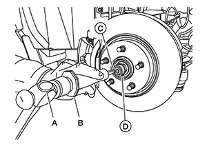
|
Tool number (B) |
: (NI-52982) |
Visually verify that staked area
(A) of wheel hub lock nut (B) is completely released from front drive
shaft (1) or damage to drive shaft can occur. 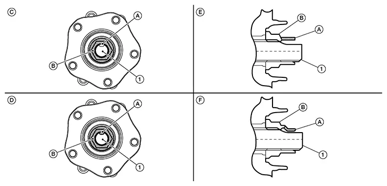
|
(C) |
: Fully released |
|
(D) |
: Not fully released |
|
(E) |
: Fully released (sectional view) |
|
(F) |
: Not fully released (sectional view) |
Warning:
To avoid risk of death or severe personal injury:
-
Be sure that staked area of wheel hub lock nut is fully released or damage to drive shaft can occur.
-
Do not damage front drive shaft threads
Loosen wheel hub lock nut from drive shaft.
Warning:
To avoid risk of death or severe personal injury:
-
Do not use power tool.
-
Do not damage front drive shaft threads.
-
Do not reuse drive shaft lock nut.
-
When loosening lock nut, if it does not turn smoothly, verify that staked area is completely released.
Using a piece of wood and a suitable
tool, tap on the wheel hub lock nut to disengage the drive shaft from
the wheel hub and bearing. 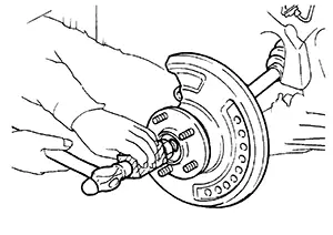 Note:
Note: 
Use suitable puller if the drive shaft cannot be separated from wheel hub and bearing assembly.
Remove the wheel hub lock nut.
Warning:
To avoid risk of death or severe personal injury:
-
Do not reuse wheel hub lock nut.
Apply a moderate coat of paste [service
parts (440037S000)] to bearing surface (A) as shown. 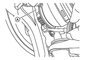 Note:
Note:
Always check with the Parts Department for the latest parts information.
Install new wheel hub lock nut.
Warning:
To avoid risk of death or severe personal injury:
-
Do not reuse wheel hub lock nut.
Hold wheel hub and bearing using a suitable tool. Tighten wheel hub lock nut to specification.
|
Wheel hub lock nut |
165 N·m (17 kg−m, 122 ft−lb) |
Warning:
To avoid risk of death or severe personal injury:
-
Since drive shaft is assembled by press-fitting, use a torque wrench to tighten wheel hub lock nut. Do not use a power tool.
-
Too much torque causes axle noise. Too little torque causes wheel bearing looseness.
Using suitable Tool (A) and cold
chisel (B) stake the wheel hub lock nut (C) as shown. 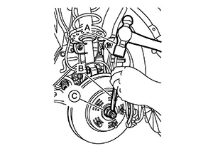
Warning:
To avoid the risk of death or severe personal injury:
-
Use the following range when staking the wheel hub lock nut.
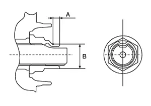
|
(A) |
: 6.2 mm (0.244 in) |
|
(B) |
: 26.4 - 27.8 mm (1.039 - 1.094 in) |
Install wheel and tire. Refer to Removal and Installation.
Front Drive Shaft. Inspection. Inspection
Inspection
Check the following items, and replace the part if necessary.
Check drive shaft mounting point and joint for looseness and other damage.
CAUTION:
Replace entire drive shaft assembly when noise or vibration occurs from drive shaft.
Check boot for cracks and other damage.
Other materials:
U2141 Can Comm Err (tcm)
Dtc Description
DTC Description
DTC DETECTION LOGIC
DTC No.
CONSULT screen
terms
(Trouble
diagnosis content)
DTC detection condition
...
Laser/radar (distance Sensor)
C2580-44 Control Unit
Dtc Description
DTC Description
DTC DETECTION LOGIC
DTC
CONSULT screen terms
(Trouble diagnosis
content)
DTC dete ...
Abs Warning Lamp
Component Function Check
Component Function Check
CHECK ABS WARNING LAMP FUNCTION
Check that ABS warning lamp in combination meter
turns ON for 1 second after ignition switch is placed ON.
CAUTION:
Never start th ...