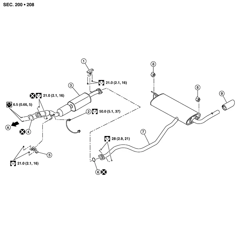
Nissan Sentra B18 (2020-2025) Service Manual: Exploded View
|
1. |
Mounting rubber |
2. |
Heated oxygen sensor 2 |
3. |
Exhaust front tube |
|
4. |
Plate gasket |
5. |
Mounting rubber |
6. |
Seal bearing |
|
7. |
Exhaust main muffler |
8. |
Mounting rubber |
9. |
Exhaust finisher (if equipped) |
|
A. |
To exhaust manifold. Refer to Exploded View. |
CAUTION:
Do not remove the heated oxygen sensor 2 from the front exhaust tube unless necessary for replacement of the heated oxygen sensor 2. If the heated oxygen sensor 2 is removed from the front exhaust tube, it must be replaced with a new one.
Note:
Heated oxygen sensor 2 replacement or removal from the front exhaust tube is not necessary when removing or repositioning the front exhaust tube. Disconnect the harness connector from the heated oxygen sensor 2 and remove or reposition the front exhaust tube and the heated oxygen sensor 2 as an assembly.
 Exhaust System
...
 Removal and Installation
Removal and Installation
REMOVAL
Disconnect each joint and mounting rubber.
Remove heated oxygen sensor 2 (1) using Tool
(A).
:
Front
...
Other materials:
Cooling fan control
SYSTEM DIAGRAM
SYSTEM DESCRIPTION
ECM controls cooling fan speed corresponding to vehicle speed, engine coolant
temperature, refrigerant pressure,
air conditioner ON signal. Then control system has 3-step control
[HIGH/LOW/OFF].
Cooling Fan Operation
Cooling Fan Relay Operation
Whe ...
B24a4-11 Intake Sensor
Dtc Description
DTC Description
DTC DETECTION LOGIC
DTC No.
CONSULT screen terms
(Trouble diagnosis content)
DTC detection condition
...
P2769-00 Torque Converter Clutch
Dtc Description
DTC Description
DTC DETECTION LOGIC
DTC
CONSULT screen terms
(Trouble diagnosis
content)
DTC detection
conditi ...
