Nissan Sentra Service Manual: Evaporative emission system
EVAPORATIVE EMISSION SYSTEM : System Description
SYSTEM DIAGRAM
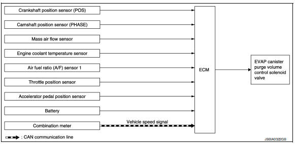
INPUT/OUTPUT SIGNAL CHART
| Sensor | Input signal to ECM | ECM function | Actuator | |
| Crankshaft position sensor (POS) | Engine speed* | EVAP canister purge flow control | EVAP canister purge volume control solenoid valve | |
| Camshaft position sensor (PHASE) | ||||
| Mass air flow sensor | Amount of intake air | |||
| Engine coolant temperature sensor | Engine coolant temperature | |||
| Air fuel ratio (A/F) sensor 1 | Density of oxygen in exhaust gas (Mixture ratio feedback signal) | |||
| Throttle position sensor | Throttle position | |||
| Accelerator pedal position sensor | Accelerator pedal position | |||
| Battery | Battery voltage* | |||
| Combination meter | CAN communication | Vehicle speed signal | ||
*: ECM determines the start signal status by the signals of engine speed and battery voltage.
SYSTEM DESCRIPTION
The evaporative emission system is used to reduce hydrocarbons emitted into the atmosphere from the fuel system. This reduction of hydrocarbons is accomplished by activated charcoals in the EVAP canister.
The fuel vapor in the sealed fuel tank is led into the EVAP canister which contains activated carbon and the vapor is stored there when the engine is not operating or when refueling to the fuel tank.
The vapor in the EVAP canister is purged by the air through the purge line to the intake manifold when the engine is operating. EVAP canister purge volume control solenoid valve is controlled by ECM. When the engine operates, the flow rate of vapor controlled by EVAP canister purge volume control solenoid valve is proportionally regulated as the air flow increases.
EVAP canister purge volume control solenoid valve also shuts off the vapor purge line during decelerating and idling.
 Starter motor drive control
STARTER MOTOR DRIVE CONTROL : System Description
SYSTEN DIAGRAM
*1: CVT models
*2: M/T models
INPUT/OUTPUT SIGNAL CHART
Sensor
Input signal to ECM
ECM function
Actuator
...
 Automatic speed control device (ASCD)
AUTOMATIC SPEED CONTROL DEVICE (ASCD) : System Description
SYSTEM DIAGRAM
BASIC ASCD SYSTEM
Refer to Owner's Manual for ASCD operating instructions.
Automatic Speed Control Device (ASCD) all ...
Other materials:
Three-way catalyst
The three-way catalyst is an emission control
device installed in the exhaust system. Exhaust
gases in the three-way catalyst are burned at
high temperatures to help reduce pollutants.
WARNING
The exhaust gas and the exhaust system
are very hot. Keep people, animals
or flammab ...
Front regulator
Exploded View
Front door panel
Front door glass channel front
Front door glass regulator
Front door glass regulator motor
Front door glass channel rear
Front door glass
Front door glass rubber run
Removal and Installation
REMOVAL
WARNING:
Before servicing, turn ignition ...
VDC/TCS/ABS
Symptom Table
If ABS warning lamp and SLIP indicator lamp turn ON, perform
self-diagnosis.
NOTE:
1: The ABS does not operate when the speed is 10 km/h
(6 MPH) or less.
2: Under the following conditions, ABS is activated
and vibration is felt when brake pedal is lightly depr ...
