Nissan Sentra Service Manual: EPS branch line circuit
Diagnosis procedure
1.Check connector
- Turn the ignition switch off.
- Disconnect the battery cable from the negative terminal.
- Check the terminals and connectors of the EPS control unit for damage, bend and loose connection (unit side and connector side).
Is the inspection result normal? Yes >> go to 2.
No >> repair the terminal and connector.
2.Check harness for open circuit
- Disconnect the connector of EPS control unit.
- Check the resistance between the eps control unit harness connector terminals.
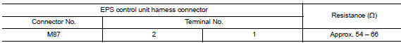
Is the measurement value within the specification? YES >> GO TO 3.
NO >> Repair the EPS control unit branch line.
3.Check power supply and ground circuit
Check the power supply and the ground circuit of the eps control unit. Refer to stc-22, "diagnosis procedure".
Is the inspection result normal? Yes (present error)>>replace the eps control unit. Refer to stc-39, "removal and installation".
Yes (past error)>>error was detected in the eps control unit branch line.
No >> repair the power supply and the ground circuit
 Dlc branch line circuit
Diagnosis procedure
1.Check connector
Turn the ignition switch off.
Disconnect the battery cable from the negative terminal
Check the terminals and connectors of the data link connector for d ...
 M&A branch line circuit
Diagnosis procedure
1.Check connector
Turn the ignition switch off.
Disconnect the battery cable from the negative terminal.
Check the terminals and connectors of the combination meter for da ...
Other materials:
Brake booster
Exploded View
Master cylinder assembly
Brake booster
Lock nut
Clevis
Gasket
Spacer
Removal and installation
REMOVAL
Remove cowl top and cowl top extension. Refer to EXT-26, "Removal and
Installation".
Remove air duct and air cleaner case. Refer to EM-25, &qu ...
B0028 Side airbag module RH
Description
DTC B0028 FRONT RH SIDE AIR BAG MODULE
The front RH side air bag module is wired to the air bag diagnosis sensor
unit. The air bag diagnosis sensor
unit will monitor for opens and shorts in detected lines to the front RH side
air bag module.
PART LOCATION
Refer to SRC-5, " ...
Rear disc brake
BRAKE PAD
BRAKE PAD : Exploded View
Upper sliding pin bolt
Lower sliding pin bolt
Bushing
Cylinder body
Inner shim cover
Inner shim
Inner pad (with pad wear sensor)
Pad retainer
Torque member
Outer pad
Outer shim
Outer shim cover
Apply rubber grease
Molykote A ...
