Nissan Sentra Service Manual: Engine assembly CVT
CVT : Exploded View
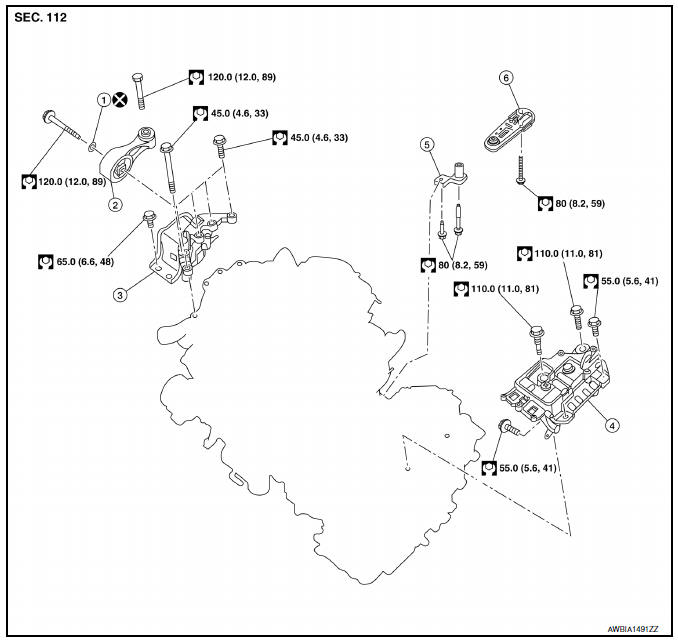
- Washer
- Upper torque rod (RH)
- Engine mounting insulator (RH)
- Engine mounting insulator (LH)
- Rear torque rod bracket
- Rear torque rod
CVT : Removal and Installation
WARNING:
- Situate the vehicle on a flat and solid surface.
- Place chocks at front and back of rear wheels.
- Attach proper slingers and bolts described in PARTS CATALOG if engine slingers are not equipped.
CAUTION:
- Always be careful to work safely, avoid forceful or uninstructed operations.
- Do not start working until exhaust system and coolant are cool enough.
- If items or work required are not covered by the engine section, refer to the applicable sections.
- Always use the support point specified for lifting.
- Use either 2-pole lift type or separate type lift as best you can. If board-on type is used for unavoidable reasons, support at the rear axle jacking point with a transmission jack or similar tool before starting work, in preparation for the backward shift of center of gravity.
- For supporting points for lifting and jacking point at rear axle, refer to GI-31, "Garage Jack and Safety Stand and 2-Pole Lift".
NOTE:
When removing components such as hoses, tubes/lines, etc., cap or plug openings to prevent fluid from spilling.
REMOVAL
Outline
Remove the engine and the transaxle assembly from the vehicle downward. Separate the engine and the transaxle.
- Remove hood assembly. Refer to DLK-149, "HOOD ASSEMBLY : Removal and Installation".
- Release fuel pressure. Refer to EC-143, "Work Procedure".
- Remove battery and battery tray. Refer to PG-50, "Exploded View".
- Remove engine room cover. Refer to EM-24, "Exploded View".
- Remove cowl top. Refer to EXT-26, "Removal and Installation".
- Remove air cleaner body. Refer to EM-25, "Exploded View".
- Remove engine under cover. Refer to EM-24, "Exploded View".
- Drain engine coolant from radiator. Refer to CO-12, "Changing Engine Coolant".
CAUTION:
- Perform this step when the engine is cold.
- Do not spill engine coolant on drive belts.
- Remove front wheels and tires (RH/LH) using power tool. Refer to WT-47, "Adjustment".
- Remove front fender protector side covers (RH). Refer to EXT-27, "FENDER PROTECTOR : Exploded View".
- Remove drive belt. Refer to EM-15, "Removal and Installation".
- Disconnect vacuum hose from intake manifold. Refer to EM-27, "Exploded View".
- Remove radiator hose (upper and lower). Refer to CO-15, "Exploded View".
- Remove radiator and fan shroud and motor assembly. Refer to CO-15, "Exploded View".
- Remove TCM and bracket. Refer to TM-263, "Exploded View".
- Remove ECM bracket, and then temporarily secure the engine harness on the engine side.
CAUTION:
Protect harness connectors using a resin bag against foreign materials during the operation.
- Disconnect fuel feed hose quick connector. Refer to EM-40, "Exploded View".
- Disconnect heater hoses. Refer to CO-24, "Exploded View".
- Disconnect control cable from transaxle. Refer to TM-256, "Exploded View".
- Disconnect lines from CVT oil warmer. Refer to TM-273, "Exploded View".
- Remove EVAP hoses. Refer to FL-14, "Exploded View".
- Remove A/C compressor bolts and position A/C compressor aside. Refer to HA-30, "Exploded View".
- Remove ground cable at engine side.
- Remove ground cable at transaxle side.
- Remove drive shafts (RH/LH). Refer to FAX-25, "EXCEPT 6M/T : Exploded View".
- Remove exhaust front tube. Refer to EX-5, "Exploded View".
- Remove rear cover plate.
- Remove torque converter nuts.
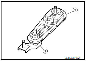
- Remove rear torque rod (1) and torque rod bracket (2).
- Remove stabilizer connecting rod. Refer to FSU-12, "Exploded View".
- Remove front suspension member. Refer to FSU-16, "Exploded View".
- Preparation for the separation work of transaxle is as follows:
- Remove transaxle joint bolts which pierce at oil pan (upper) lower rear side. Refer to EM-33, "Exploded View".
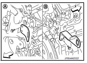
- Install engine slinger to front cover front (LH) side (A) and cylinder head rear (RH) side (B).
Slinger bolts
Front cover front (LH) side: : 32.9 NВ·m (3.4 kg-m, 24 ft-lb)
Cylinder head rear (RH) side: : 25.0 NВ·m (2.6 kg-m, 18 ft-lb)
- Support engine and transaxle assembly with engine lifting equipment from the top with the vehicle raised on a hoist.
- Use a manual lift table caddy (A) or equivalent rigid tool such as a transmission jack. Securely support bottom of the engine and the transaxle assembly.
CAUTION:
Put a piece of wood or equivalent as the supporting surface, secure a completely stable condition.
- Remove upper torque rod (1) and engine mounting insulator (RH) (2).
- Remove engine mounting insulator (LH).
- Carefully lower jack, or raise lift to remove the engine and the transaxle assembly. When performing work, observe the following caution.
CAUTION:
- Check that no part interferes with the vehicle side.
- Before and during this lifting, always check if any harnesses are left connected.
- During the removal, always be careful to prevent the vehicle from falling off the lift due to changes in the center of gravity.
- If necessary, support the vehicle by setting jack or suitable tool at the rear.
- Remove starter motor. Refer to STR-30, "Exploded View".
- Lift with a hoist and separate the engine from the transaxle assembly. Refer to TM-28, "Exploded View".
INSTALLATION
Installation is in the reverse order of removal.
NOTE:
Tighten all mounts to specification.
CAUTION:
- Do not allow engine oil to get on engine mounting insulator. Be careful not to damage engine mounting insulator.
- Check that each mounting insulator is seated properly, and tighten nuts and bolts.
- When installation directions are specified, install parts according to the direction marks on them referring to the illustration of components. Refer to EM-86, "CVT : Exploded View".
CVT : Inspection
INSPECTION AFTER INSTALLATION
- Before starting engine, check oil/fluid levels including engine coolant and engine oil. If less than required quantity, fill to the specified level. Refer to MA-11, "Fluids and Lubricants".
- Use procedure below to check for fuel leakage
- Turn ignition switch “ON” (with engine stopped). With fuel pressure applied to fuel piping, check for fuel leakage at connection points.
- Start engine. With engine speed increased, check again for fuel leakage at connection points.
- Run engine to check for unusual noise and vibration.
NOTE:
If hydraulic pressure inside timing chain tensioner drops after removal and installation, slack in the guide may generate a pounding noise during and just after engine start. However, this is normal. Noise will stop after hydraulic pressure rises.
- Warm up engine thoroughly to check there is no leakage of fuel, exhaust gases, or any oil/fluids including engine oil and engine coolant.
- Bleed air from lines and hoses of applicable lines, such as in cooling system.
- After cooling down engine, again check oil/fluid levels including engine oil and engine coolant. Refill to the specified level, if necessary.
- Summary of the inspection items:
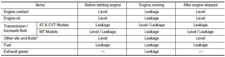
*: Power steering fluid, brake fluid, etc.
 Engine assembly M/T
M/T : Exploded View
Washer
Upper torque rod (RH)
Engine mounting insulator (RH)
Rear torque rod bracket
Rear torque rod
Engine mounting bracket (LH)
Engine mounting frame support ...

Other materials:
Parking brake system
Inspection and Adjustment
INSPECTION
Lever Stroke
Operate the parking brake lever with a force of 196 N (20.0
kg-f, 44.1 lb-f). Check that the lever stroke is
within the specified number of notches. (Check it by listening to the clicks
of the ratchet.)
Number of notches : Refer t ...
Ambient sensor signal circuit
Description
It detects outside air temperature and converts it into a resistance value
which is then input into the combination
meter.
Diagnosis Procedure
Regarding wiring diagram information, refer to mwi-28, "wiring diagram".
1.Check ambient sensor signal circuit
Turn igniti ...
Power outlet
Center Console
Console Box (if so equipped)
The power outlets are for powering electrical
accessories such as cellular telephones. They
are rated at 12 volt, 120W (10A) maximum.
The power outlets are powered only when the
ignition switch is in the ACC or ON position.
CAUTION
The ...
